HP 560 Wireless 802.11ac Access Point Quickstart 3 Installation
Installation
The AP can be mounted on a wall, a wall-mounted electrical box, or a
suspended ceiling. The AP Bracket is mounted first, and then the AP is
attached to the bracket. The AP Bracket is two-sided: The AP is installed on the
side with the UP arrow. The other side, with the T-bar clip screw holes, faces
the wall or T-bar.
Mounting directly on a wall
1. Hold the AP bracket with the UP arrow pointing up against the wall where
you want to install it. Mark the location of the screw holes (3) and the
cutout area (7).
2. Drill two holes for the wall anchors, typically 4.7 mm (3/16 inch) in
diameter.
3. If necessary, drill a hole for the Ethernet cable in the marked cutout area
of the AP Bracket. Alternatively, you can feed the Ethernet cable from
above and through the AP cable channel.
4. Insert the anchors and tap them flush with the wall surface.
5. Pull the Ethernet cable through the hole in the wall and the AP Bracket.
6. Use the mounting screws to attach the AP Bracket to the wall. Proceed to
Attach the AP on page 4.
Mounting on an electrical box
1. Disconnect power and take any other needed security precautions.
2. Remove the electrical box cover and any contents.
3. Pull the Ethernet cable down into the box and through the hole in the AP
Bracket.
4. Hold the AP Bracket against the box orienting the UP arrow, and attach
the AP Bracket to the box using the countersunk screws. Proceed to
Attach the AP on page 4.
Mounting on a suspended ceiling
The AP can be mounted on a suspended ceiling using T-bar clips. Two sets of
T-bar clips are provided, a 12.5 mm set for recessed tiles and a 4.5 mm set for
flush-mount tiles.
1. Slide one of the T-bar clips into the AP Bracket T-bar slot. Attach it using
two self-tapping screws. Select the screw holes marked according to the
width of your T-bar: 9/16 in, 15/16 in, or 1.5 in. (The other T-bar clip
attaches to the AP Bracket from above the false ceiling, after the bracket
is in place on the T-bar.)
➅
➀
➁
➂
➀
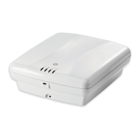
➀
AP Bracket (AP side left, wall/
ceiling side right, partial view)
1: AP retention tabs
2: Adapter Bracket mounting holes
3: Drywall mounting holes
4: AP Bracket lock tab
5: AP Bracket latch
6: Electrical box mounting holes
7: Cutout area
8: T-bar clip screw holes
➃
➂
➆
➇
➄
➀
➅
➇ ➇
➇
➁
➁➁
➂
➂
➆
➁➁
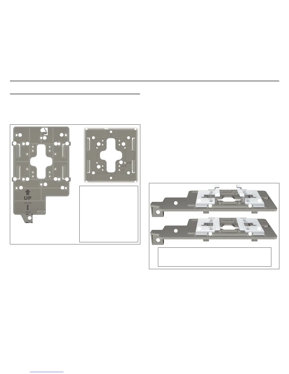
T-bar clips for ceiling mount
1: AP Bracket
2: Recessed tile 12.5 mm T-bar clip
➀
➀
➂
➃➃
➃➃
➂
3: Flat tile 4.5 mm T-bar clip
4: AP Bracket T-bar slot
 Loading...