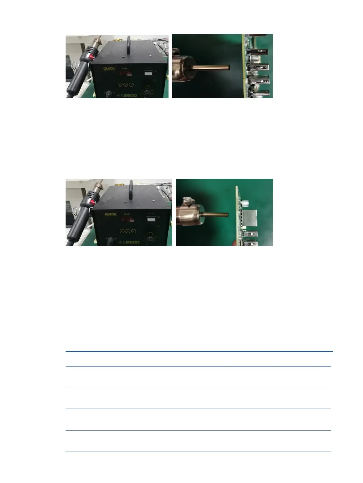
1) Use a hot air gun to melt the solder on the pins from the bottom side.
2) Lift the USB-A connector from the PCB.
3) Place the new component on the PCB. Be sure that it matches the PCB footprint.
4) Solder the new component
RJ45 connector LAN1
Repair the RJ45 connector:
1) Use a hot air gun to melt the solder on the pins from the bottom side.
2) Lift the RJ45 connector from the PCB.
3) Place the new component on the PCB. Be sure that it matches the PCB footprint.
4) Solder the new component.
Function test
After repair, be sure to confirm that all functions are working.
 Loading...