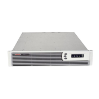
Switching on the ERM circuit breaker
Charging the ERM batteries
Connect the UPS to a grounded utility power outlet. When the
UPS is plugged in, the unit automatically enters Standby mode
and begins charging the ERM batteries. Allow 24 hours for
the ERM to fully charge.
Configuring the UPS
NOTE: If the UPS firmware version is 2.00 or later,
follow the instructions in “Configuring the UPS.” If the
UPS firmware version is earlier than 2.00, or the ERM
cannot be configured from the UPS front panel, use
the ERM configurator tool. To update the UPS
firmware or download the ERM configurator tool, see
the HP website
(http://www.hp.com/go/rackandpower
).
After the ERMs are installed, place the UPS in Configure
mode, and use the UPS front panel controls and LED
indicators to configure the UPS for the number of attached
ERMs. Other UPS parameters that can also be configured are
the nominal utility voltage level and Site Wiring Fault
detection.
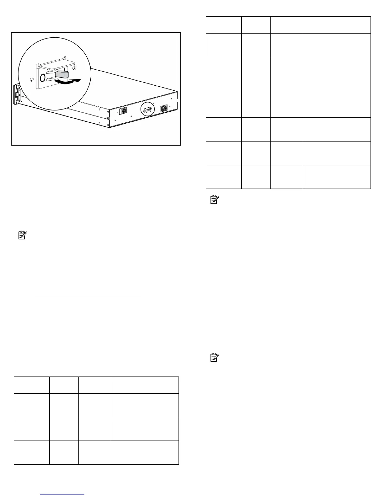
In Configure mode, the LED front panel display changes
function to enable modification of the UPS parameters. Each
LED is associated with a different parameter.
Available
settings
Parameter
Associated
LED
Explanation (when LED is
illuminated)
Nominal
voltage
setting
100/200-
208 Nom
General
Alarm (red)
Nominal utility voltage
level is set to 100/200-
208 VAC
110/220
Nom
On Battery
(red)
Nominal utility voltage
level is set to 110/220
VAC
120/230
Nom
Battery
Fault (red)
Nominal utility voltage
level is set to 120/230
VAC
Available
settings
Parameter
Associated
LED
Explanation (when LED is
illuminated)
127/240
Nom
Site Wiring
Fault (red)
Nominal utility voltage
level is set to 127/240
VAC
Wiring
fault
setting
Wiring
fault
Utility
(green)
Audible alarm will sound
when ground is missing
or line and neutral
connections are reversed
(not available on the
R3000j JPN, R3000h
NA, and R3000h JPN
models)
ERM
setting
0 ERMs
0% to 25%
load
(green)
UPS is configured for no
attached ERMs (factory
default)
1 ERM
26% to
50% load
(green)
UPS is configured for 1
attached ERM
2 ERMs
51% to
75% load
(green)
UPS is configured for 2
attached ERMs
NOTE: For units factory-configured for 200 V or 208
V, the Site Wiring Fault function has been disabled. If
reconfiguring a 230 V unit to operate at 208 V, the
Site Wiring Fault function must be manually disabled.
To change the UPS configuration parameters:
1. Place the UPS in Configure mode.
The LEDs associated with the currently configured
parameters illuminate. A flashing green cursor indicates
where you are in the configuration process as you scroll
through the available settings.
2. To change the nominal voltage, press the On button to
advance the cursor to the LED associated with the
appropriate nominal voltage parameter. The selected
voltage configuration LED flashes.
3. Press the Standby button to select the nominal voltage
configuration. The LED associated with the old input
voltage parameter turns off and the LED associated with
the new input voltage parameter illuminates solid green.
NOTE: Only one nominal utility voltage can be
configured. When setting voltage configuration
parameters, selecting an On value for any one
parameter automatically sets the other possibilities to
Off.
4. To enable the Wiring Fault parameter, press the On
button to advance the cursor to the Utility LED, then press
the Standby button. The LED illuminates solid green. This
parameter is disabled by default, and should only be
enabled for line-to-neutral connections. Enabling this
feature for line-to-line power sources will cause a false
alarm.
 Loading...