i
Contents
Product overview ·························································································································································· 1
About the HP V1910 Switch Series ································································································································ 1
HP V1910-16G Switch JE005A ······································································································································ 2
Front panel ································································································································································ 2
Rear panel ································································································································································· 3
Power supply system ················································································································································ 3
Cooling system ························································································································································· 3
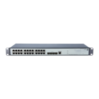
HP V1910-24G Switch JE006A ······································································································································ 3
Front panel ································································································································································ 3
Rear panel ································································································································································· 3
Power supply system ················································································································································ 4
Cooling system ························································································································································· 4
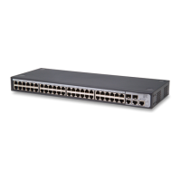
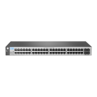
HP V1910-48G Switch JE009A ······································································································································ 4
Front panel ································································································································································ 4
Rear panel ································································································································································· 4
Power supply system ················································································································································ 4
Cooling system ························································································································································· 5
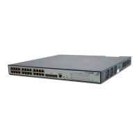
HP V1910-24G-PoE (170W) Switch JE008A ················································································································ 5
Front panel ································································································································································ 5
Rear panel ································································································································································· 5
Power supply system ················································································································································ 5
Cooling system ························································································································································· 5
HP V1910-24G-PoE (365W) Switch JE007A ················································································································ 6
Front panel ································································································································································ 6
Rear panel ································································································································································· 6
Power supply system ················································································································································ 6
Cooling system ························································································································································· 7
Ports ···················································································································································································· 7
Console port······························································································································································ 7
10/100/1000Base-T Ethernet port ······················································································································· 7
1000Base-X SFP interface ······································································································································· 7
LEDs ···················································································································································································· 9
Power LED ································································································································································· 9
RPS status LED ··························································································································································· 9
Port mode LED ························································································································································ 10
10/100/1000Base-T auto-sensing Ethernet port status LED ············································································ 10
1000Base-X SFP interface status LED ·················································································································· 11
Preparing for installation ··········································································································································· 12
Safety recommendations ··············································································································································· 12
Examining the installation site ······································································································································ 12
Temperature/humidity ·········································································································································· 12
Cleanness ······························································································································································· 13
EMI ·········································································································································································· 13
Laser safety ····························································································································································· 13
Installation tools ······························································································································································ 14
Installing the switch ···················································································································································· 15
Installation flow ······························································································································································ 15
Installing the switch into a 19-inch rack ······················································································································ 16