Pin Assignment
Table 3-9 describes the pin assignment for the core wires of an AISG multi-wire cable.
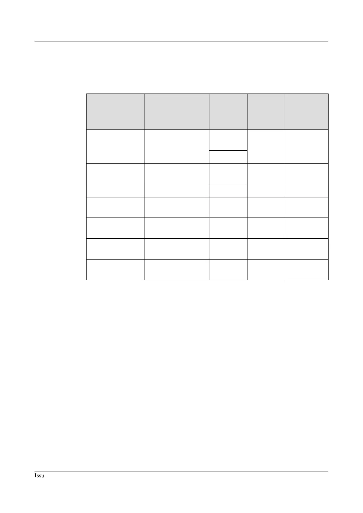
Table 3-9 Pin assignment for the core wires of an AISG multi-wire cable
X1 End (Pin of the
Waterproofed
DB9 Male
Connector)
X2 End (Pin of the
Standard AISG
Female Connector)
Color of
the Core
Wire
Type of
the Core
Wire
Description
X1.1 X2.1
White and
blue
Twisted
pair
+12 V
Blue
X1.3 X2.3 White and
orange
Twisted
pair
RS485 B
X1.5 X2.5 Orange RS485 A
X1.4 X2.4 White and
green
- GND
X1.9 is connected to
X1.4.
- - - GND
- X2.1 is connected to
X2.6.
- - +12 V
- X2.4 is connected to
X2.7.
- - GND
3.10 RRU AISG Extension Cable
This section describes the remote radio unit (RRU) AISG extension cable. When the distance
between an RRU and a remote control unit (RCU) is longer than 5 m, an AISG multi-wire cable
is not long enough to connect the RRU and the RCU. In this case, an AISG extension cable is
used to extend the AISG multi-wire cable for transmitting RS485 signals.
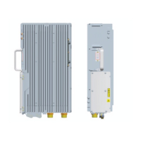
Exterior
An AISG extension cable has a standard AISG male connector at one end and a standard AISG
female connector at the other end, as shown in Figure 3-12.
DBS3900
RRU3252/RRU3256 Hardware Description 3 RRU Cables
Issue Draft A (2012-11-30) Huawei Proprietary and Confidential
Copyright © Huawei Technologies Co., Ltd.
20
 Loading...