7
ASSEMBLY
Protective gloves (not provided) should be
worn durin g assembly .
ATTACHING THE BAR & CHAIN (If not
already attached)
WARNING: Recheck each assem-
bly step if the saw is received assembled. Al-
ways wear gloves when handling the chain.
The chain is sharp and can cut you even
when it is not moving!
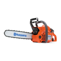
1. Loosen and remove the chain brake nuts
and the chain brake from the saw.
2. Remove the plastic shipping spacer (if
present).
Chain Brake
Chain Brake
Nuts
Bar Tool
Location of shipping spacer
3. An adjusting pin and screw is used to ad-
just the tension of the chain. It is very im-
portant when assembling the bar, that
the pin located on the adjusting screw
aligns into a hole in the bar. Turning the
screw will move the adjustment pin up
and down the screw . Locate this adjust-
ment before you begin mounting the bar
onto the saw. See illustration.
Adjustment located on Chain Brake
Inside view of
Chain Brake
4. Turn the adjusting screw by hand coun-
terclockwise until the adjusting pin just
touches the stop. This should allow the
pin to be near the correct position. Fur-
ther adjustment may be necessary as
you mount the bar.
5. Slide guide bar behind clutch drum until
guide bar stops against clutch drum
sprocket.
Mount the Bar
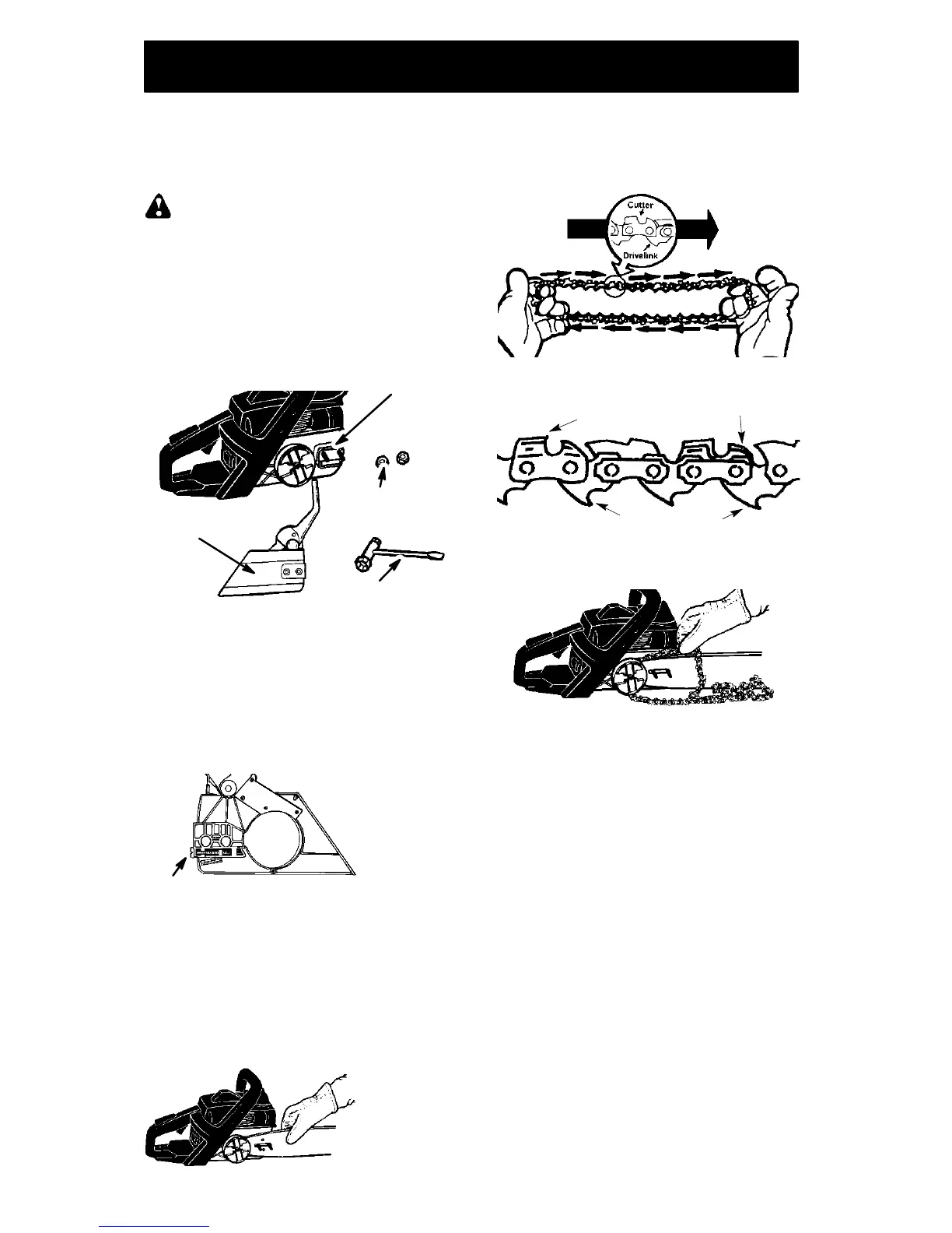
6. Prepare the chain by checking the proper
direction. Without following the illustration it
is easy to place the chain on the saw in the
wrong direction. Use the illustration of the
chain to determine the proper direction.
CUTTERS MUST FACE IN
DIIR ECTION OF R OTATION
Tip of
Bar
Cutters
Depth Gauge
Drive Links
7. Place chain over and behind clutch, fit-
ting the drive links in the clutch drum
sprocket.
Place chain onto the s
rocket
8. Fit bottom of drive links between the
teeth in the sprocket in the nose of the
guide bar.
9. Fit chain drive links into bar groove.
10. Pull guide bar forward until chain is snug
in guide bar groove. Ensure all drive
links are in the bar groove.
11. Now, install chain brake making sure the
adjusting pin is positioned in the lower
hole in the guide bar. Remember this pin
moves the bar forward and backward as
the screw is turned.
12. Install chain brake nuts and finger tighten
only. Once the chain is tensioned, you
will need to tighten chain brake nuts.
CHAIN TENSION
(Including units with chain already installed)
NOTE: When adjusting chain tension,
make sure the chain brake nuts are finger
tight only. Attempting to tension the chain
when the chain brake nuts are tight can
cause damage.
Checking the tension:
Use the screwdriver end of the bar tool to
move the chain around the bar . If the chain
does not rotate, it is too tight. If too loose, the
chain will sag below the bar.
 Loading...