20
REPAIR PARTS
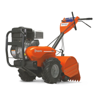
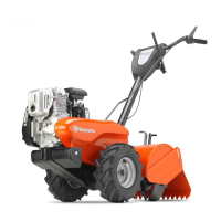
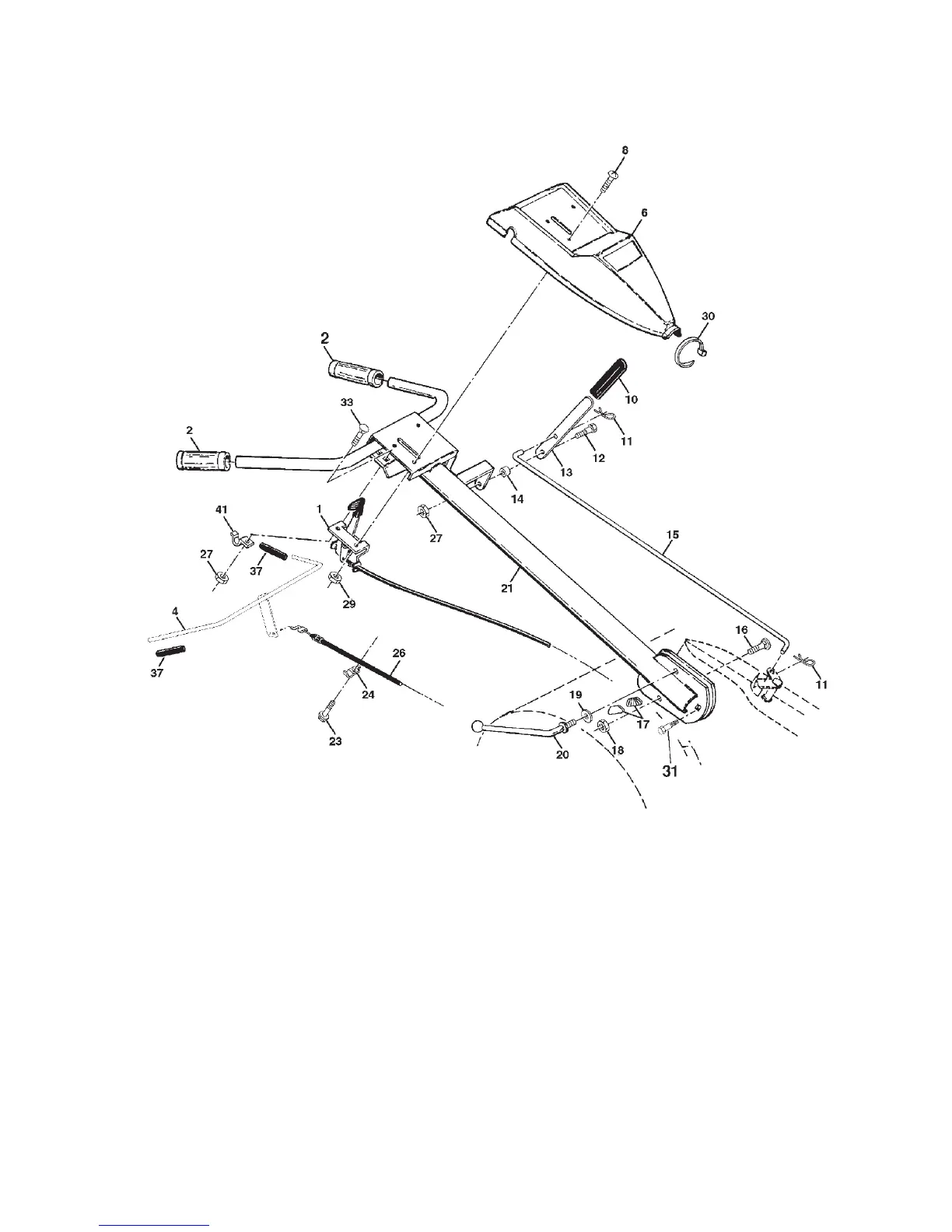
TILLER - - MODEL NUMBER 650CRTC, PRODUCT NUMBER 954 32 80-30
HANDLE ASSEMBLY
KEY PART
NO. NO. DESCRIPTION
21 532 18 11-27 Handle
23 532 08 67-77 Screw, Hex Washer Hd. Slotted
#10-24 x 1/2
24 532 00 94-84 Clip
26 532 15 92-31 Cable, Clutch
27 873 90 04-00 Nut Hex Flange 1/4-20 Unc
29 873 73 10-00 Nut, Keps #10-24 UNC
30 532 10 41-64 Tie, Cable
31 532 15 06-96 Bolt, Pivot
33 872 14 04-04 Bolt, Carriage 1/4-20 UNC x 1/2
37 532 10 26-04 Grip, Bar, Control
41 532 10 27-44 Clamp, Bar, Control
KEY PART
NO. NO. DESCRIPTION
1 532 18 06-34 Control, Throttle
2 532 00 92-66 Grip, Handle
4 532 15 92-28 Bar Assembly, Control
6 532 18 06-76 Panel, Control
8 871 19 10-08 Screw, Truss Hd. #10-24 UNC x 1/2
10 532 12 47-97 Grip, Handle
11 532 12 47-88 Clip, Hairpin
12 532 08 13-28 Bolt, Shoulder
13 532 10 93-35 Handle, Shift
14 532 10 93-13 Grommet, Rubber
15 532 10 93-37 Rod, Shift
16 872 11 06-08 Bolt, Carriage 3/8-16 x 1 Gr. 5
17 532 10 92-29 Lock, Handle
18 873 68 06-00 Nut, Crownlock 3/8-16 Unc
19 819 13 16-11 Washer 13/32 x 1 x 11 Ga.
20 532 10 92-28 Lever, Lock, Handle
NOTE: All component dimensions given in U.S. inches.
1 inch = 25.4 mm
 Loading...