4
TOOLS REQUIRED FOR ASSEMBLY
A socket wrench set will make assembly easier. Standard
wrench sizes are listed.
(1) Utility knife
(1) Tire pressure gauge
(1) Pair of pliers
(1) 9/16" wrench
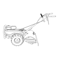
OPERATOR’S POSITION (See Fig. 1)
When right or left hand is mentioned in this manual, it
means when you are in the operating position (standing
behind tiller handles).
Your new tiller has been assembled at the factory with exception of those parts left unassembled for shipping purposes.
To ensure safe and proper operation of your tiller all parts and hardware you assemble must be tightened securely. Use
the correct tools as necessary to insure proper tightness.
FRONT
OPERATOR’S
POSITION
LEFT
RIGHT
FIG. 1
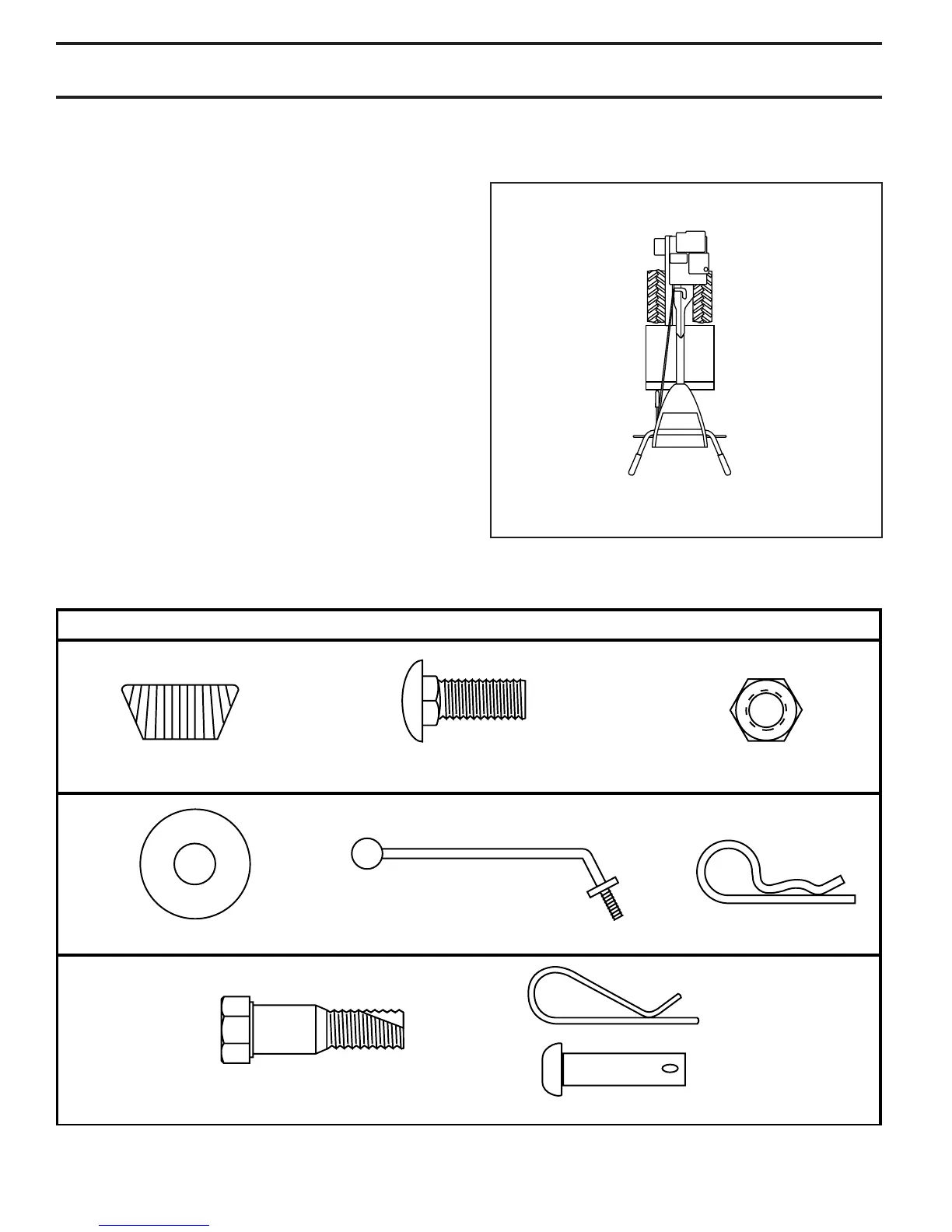
(1) Hairpin Clip
(1) Carriage Bolt
3/8-16 UNC x 1 Grade 5
(1) Center Locknut
3/8-16 UNC
(1) Handle Lock Lever
(1) Flat Washer 13/32 x 1 x 11 Gauge
CONTENTS OF HARDWARE PACK
(2) Handle Locks
(1) Pivot Bolt
3/8-16 UNC Grade 5
Extra Shear Pins & Clips
ASSEMBLY
 Loading...