4-6 601156_0110
adjusted forward and rearward by removing the locknut that
locks the seat platform in place and pivoting the seat platform
up and forward. Then loosen the four cap screws on the
underneath side of the operator’s platform. Position the seat
where you have the best control of the machine and are the most
comfortable and then tighten the cap screws. Fig. 4-9
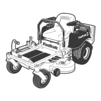
FasTrak 48/54 - The seat can be adjusted forward and
rearward by sliding the seat release handle and moving the seat
until a comfortable operating position is attained. Fig. 4-10
Steering control lever adjustment
The steering control levers can be adjusted for operator
comfort. By loosening the cap screws that attaches the upper
control lever to the lower lever (Fig. 4-11), the upper control
lever can be pivoted to fit the operator’s personal preference.
The steering control levers can also be adjusted up and down.
Remove the cap screws and slide the upper control lever up or
down and align the holes in it with the holes in lower lever. Re-
install the cap screws and tighten.
The steering control levers should be adjusted so that they
align with each other when in the neutral position.
Fig. 4-8
Fig. 4-10
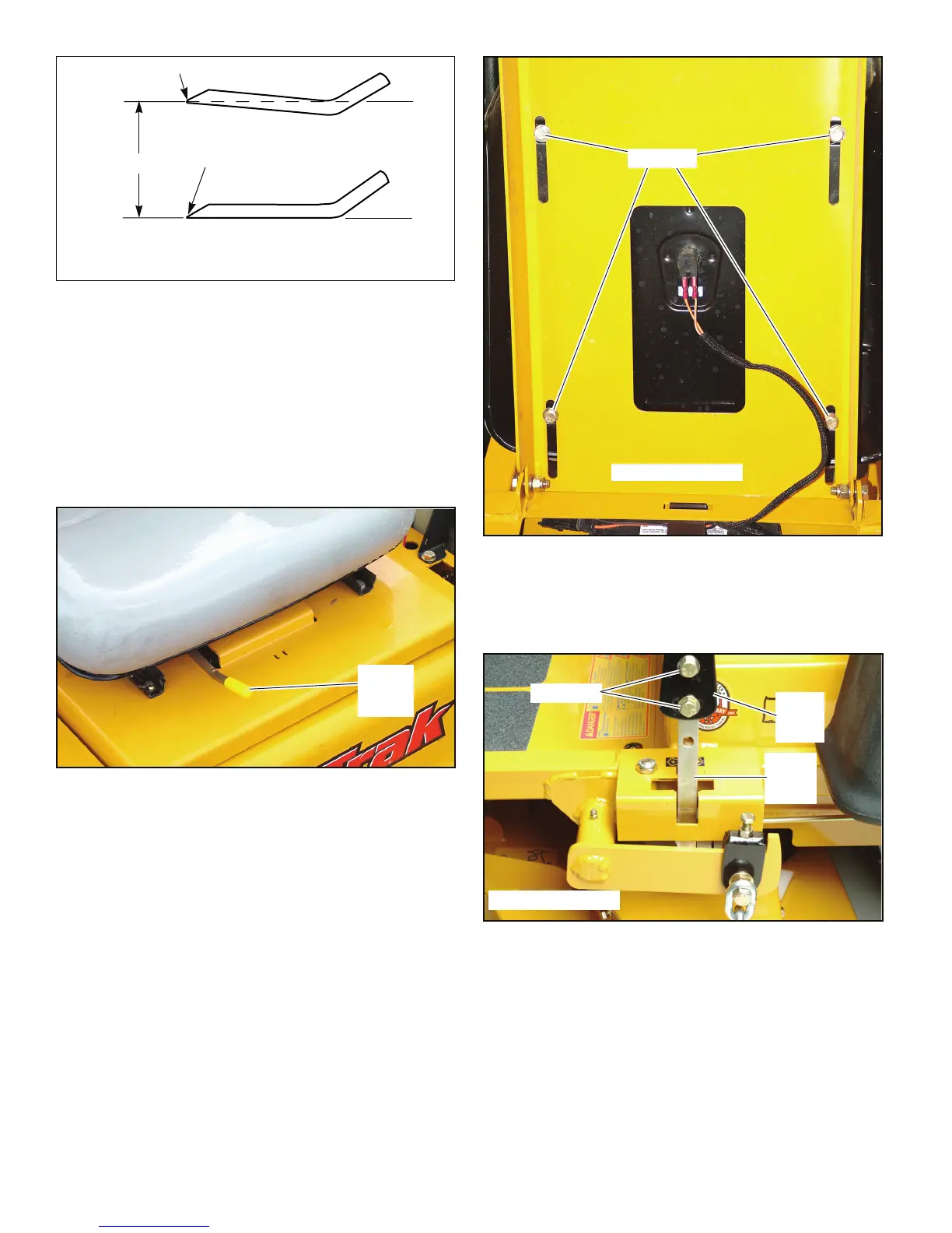
Cutting edge
Twisted Blade Edge
(replace)
Cutting edgeCutting Plane
Straight Blade Edge
End view of blades, comparing
twisted and straightened blades
Fig. 4-9
Fig. 4-11
FasTrak 36/42 shown
Cap screw
Upper
control
lever
Lower
control
lever
FasTrak 36/42 shown
Cap screw
 Loading...