MAINTENANCE
powermax30 Service Manual 3-13
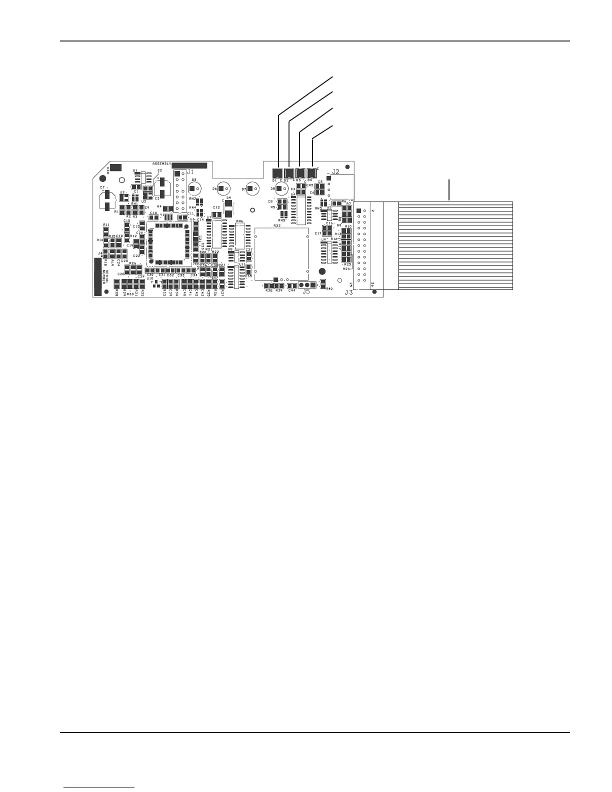
Reset/watchdog
Error
Transfer (XFR)
Start
Ribbon cable
The control board LEDs are:
• Start — The power supply has a start signal. This LED illuminates when the power supply receives a start signal
and remains illuminated during normal operation.
• Transfer — This LED illuminates when there is proper arc transfer between the torch and the workpiece, and will
flash during continuous pilot arc operation (such as when cutting expanded metal or moving the arc
off the plate and then back on).
• Error — The Error LED illuminates when the gas pressure, torch cap, or temperature LEDs on the front of the
power supply illuminate. If all 4 LEDs on the front of the power supply are flashing, the Error LED also
flashes. The number of flashes between pauses indicates which component may have failed.
• Reset — This LED illuminates when a voltage reading is out of range or the Reset LED flashes.
During normal operation, the power ON LED on the front of the power supply and the Start and Transfer LEDs on
the control board illuminate. When a problem occurs with the system, one or more of the fault LEDs on the front of
the power supply and the Error LED or the Reset LED on the control board may illuminate or flash.
Use the control board Error and Reset LEDs to troubleshoot
The Error and Reset LEDs provide information to use when troubleshooting a system failure. If the LEDs on the
front of the power supply are flashing, look at the Error LED on the control board to determine where the fault may
be. Count the number of flashes and then look at the table on the following page to determine the corrective action.
Reset LED
When the control board’s Reset LED illuminates, the voltages on the power board may be incorrect. Perform the
following tests at J7 on the power board (see
Test 2 — power board voltage checks
, later in this section):
• Test pin 5 to ground for 3.3 VDC (±10%).
• Test pin 7 to ground for 5 VDC (±10%).
• Test pin 12 to ground for 2.2 VDC (±10%).
If the values you find are not within ±10% of the above values, detach the control board’s ribbon cable and perform
the tests again. If you find the correct values the second time, replace the control board. Otherwise, replace the
power board.

 Loading...


