MAINTENANCE
powermax30 Service Manual 3-15
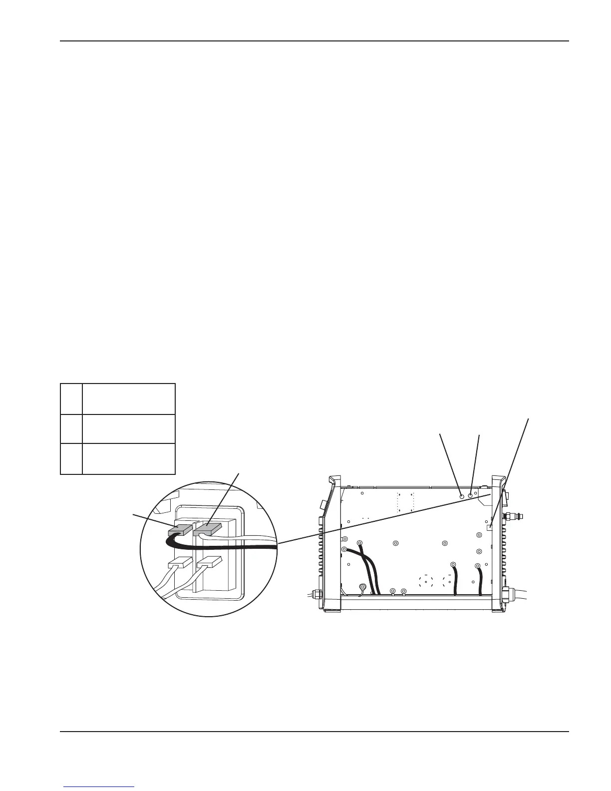
Single phase
L Black (CSA)
Brown (CE)
N White (CSA)
Blue (CE)
PE Green (CSA)
Green/yellow (CE)
L
N
PE (ground)
J2
J1
Test 1 – voltage input
Check the incoming voltage and the line voltage to the top of the power switch (S1).
1. Disconnect the electrical power and set the ON/OFF switch to OFF (O).
2. Ease the ON/OFF switch’s top 2 wires out from the tabs a little ways so that you can get your test leads on the
tabs to check the AC voltage.
3. Once you have your test leads in place, reconnect the electrical power. Leave the ON/OFF switch set to OFF.
The voltage should equal the line voltage of the incoming circuit, for example 120 V or 240 V
4. If the AC voltage is incorrect, check to see that you have power to the unit. If you do have power, check the
power cord for damage.
5. If the power source and power cord are functioning correctly, disconnect the electrical power again and
reconnect the wires.
6. Reconnect the electrical power. Then set the ON/OFF switch to ON (I), and measure the AC voltage from J1 to
J2 (labeled “AC” on the power board). This value should be the same as the incoming line voltage. If it is not,
check the ON/OFF switch.
7. If the AC LED is still illuminated, perform test 2 to determine whether the power board or the control board is
faulty.
Note: All values can be ±15%.

 Loading...


