MAINTENANCE
3-16 powermax30 Service Manual
Test 2 – power board voltage checks
With the power ON, use a meter to verify the voltages at the J7 pins listed in the following table to be certain that
the power board is functioning correctly. If any of the values are incorrect, replace the power board.
Note: All values can be ±10%.
J7 pin number to
ground
Test Expected value
19 VACR (rectified AC line voltage)
0.86 V @ 120 line voltage
1.87 V @ 230 line voltage
21 VBUS (DC bus voltage) 2.28 VDC @ 375 VBUS
18 IPFC (input current) < 0.1 VDC
20 IFB (output current) < 0.1 VDC
22 ITF (transfer current) < 0.1 VDC
5 3.3 VDC 3.3 VDC ±5%
7 5 VDC 5 VDC ±5%
12 24 V sense pin 2.2 VDC
16 Start signal
3.2 VDC closed
0 VDC open
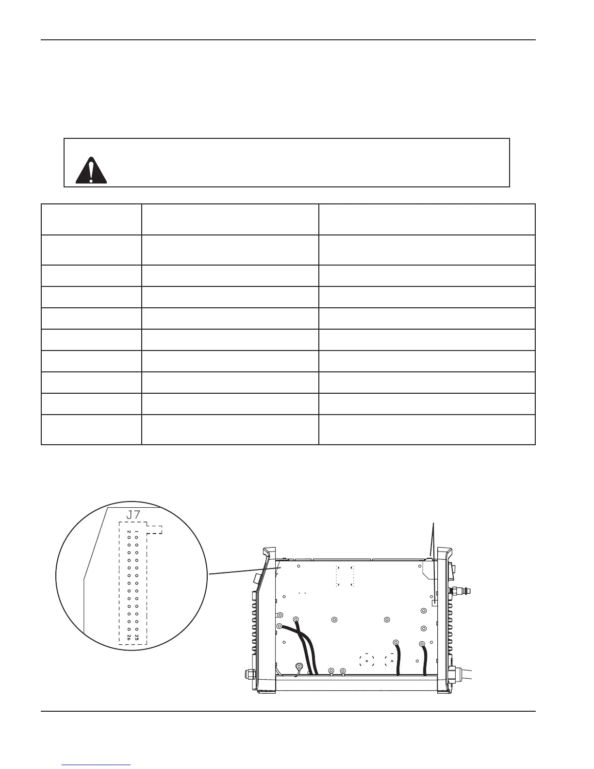
Note: To test the values at pin 16, you must have the torch and power supply positioned such that you can
safely pull and release the torch’s trigger.
Ground to the ground wire
clip or to the heat sink
Caution: Do not use -VBUS as ground. Doing so could destroy the power supply. Instead
ground to either the ground wire clip on the rear endcap or to the heat sink as
shown below.

 Loading...


