EasyManuals Logo
Home>Hypertherm>Welding System>Powermax105

Hypertherm Powermax105 Field Service Bulletin

Hypertherm Powermax105
40 pages
To Next Page IconTo Next Page
To Previous Page IconTo Previous Page
Page #11 background imageLoading...
Page #11 background image
Machine Interface Receptacle with Voltage Divider PCB
Powermax65/85/105/125, Powermax65/85/105 SYNC Field Service Bulletin 806980 11
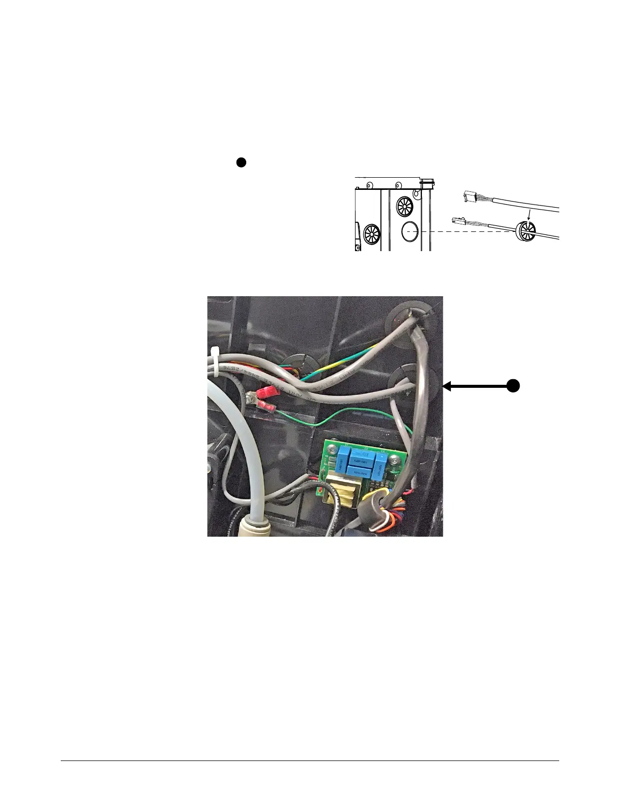
Attach the machine interface cables to the power PCB
If you have a Powermax105, Powermax125, or Powermax105 SYNC, go to page 14.
Powermax65/85 and Powermax65/85 SYNC
1. From the fan side of the plasma power supply, put the 2-pin connector and the 4-pin connector
through the right grommet .
a. Remove the grommet from the middle
panel.
b. Put the cables in the slot in the
grommet.
c. Put the connectors through the hole in
the middle panel.
d. Install the grommet in the middle panel.
1
1

Table of Contents

Other manuals for Hypertherm Powermax105

Questions and Answers:

Question and Answer IconNeed help?

Do you have a question about the Hypertherm Powermax105 and is the answer not in the manual?

Hypertherm Powermax105 Specifications

General IconGeneral
BrandHypertherm
ModelPowermax105
CategoryWelding System
LanguageEnglish

Related product manuals