MAINTENANCE
powermax1650 Service Manual
3-11
0
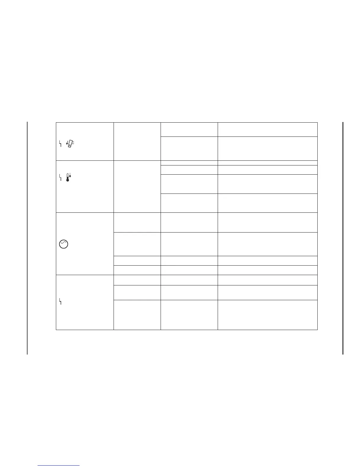
Consumables not installed,
installed improperly, or
dama
ed
Refer to consumable diagram for proper installation.
Try new consumables.
Damage to safety circuit Remove torch. Check torch end of connector. Install
consumables and check continuity on J18, pins 11 and
12 orange and blue wires. If open circuit, inspect torch
and lead assembly. Replace lead or cap switch as
necessar
cle Allow unit to cool. Sta
cle limits in manual.
Fan not operating or
improperl
Disconnect J2 and jump pins 1 and 2. Fan should
operate.
Defective heatsink temperature
switch TP1 (check when
system is cool, at least 15 min
after use
Remove J2 from power board (PCB2). Check
temperature PCB (PCB4) by checking resistance on
pins 1 and 2. If resistance is not between 3k-5k ohms,
replace temperature sensor PCB
.
Defective power transformer
(T2) temperature sensor TS2
(check when system is cool, at
least 60 min after use
Check transformer sensor (T2) by checking resistance
on J21 pins 1 and 2 on wires. If greater than 15 k
ohms, replace power transformer.
Start signal not being
received by power
supply. Start LED off on
control board (PCB3).
Damage to torch and lead
assembly.
Remove torch. Check J18 pins 10 and 12 violet and
orange wires for continuity when torch trigger is
depressed. If open circuit, inspect torch and lead
assembly.
Solenoid valve not
working
Valve stuck or no voltage to
valve
Check voltage at valve. Remove connector J21 from
valve, turn current adjust knob to test flow and check
for 24 VDC at connector J21 pins 1 and 3. If no
voltage, replace power board. If voltage, clear air lines
or replace valve.
Damaged torch or lead
assembl
Torch plunger stuck open or
broken torch leads
Verify fault: control board (PCB3) TSO LED illuminated.
Inspect torch and lead assembl
Defective control board Replace board.
Worn or bad
consumables
Overuse or improperly installed
consumables
Replace consumables.
Insufficient air flow Improper pressure setting Turn current adjustment knob to test flow and set
pressure regulator 75 psi (5.2 bar) for cutting and 50
psi (3.4 bar) for gouging.
No output from power
board (PCB2)
Power board failure, or
damaged torch or lead
assembly.
Verify fault: control board (PCB3) IF LED. If Fault and
IF LEDs are illuminated, replace power board. If IF LED
is not illuminated, replace torch and lead assembly.
NOTE: OCV is 300VDC but is only available for 100
msec. Measure at J15 and J16 using a Fluke 87 or
equivalent digital multi-meter.
Power LED illuminates, all
fault LEDs extinguished, but
no air flow or firing of torch
when torch switch is pressed
When pressing torch
trigger/start switch, air flows
from torch, but no arc
Yellow cap sensing LED
illuminates
Safety circuit not satisfied
Over temp LED illuminates Temperature sensors not
satisfied
AC

 Loading...