2 Powermax45/45 XP Field Service Bulletin 807990
Powermax45/45 XP Snubber Resistor Replacement Kit
Remove the power supply cover and component barrier
1. Turn OFF the power, disconnect the power
cord, and disconnect the gas supply.
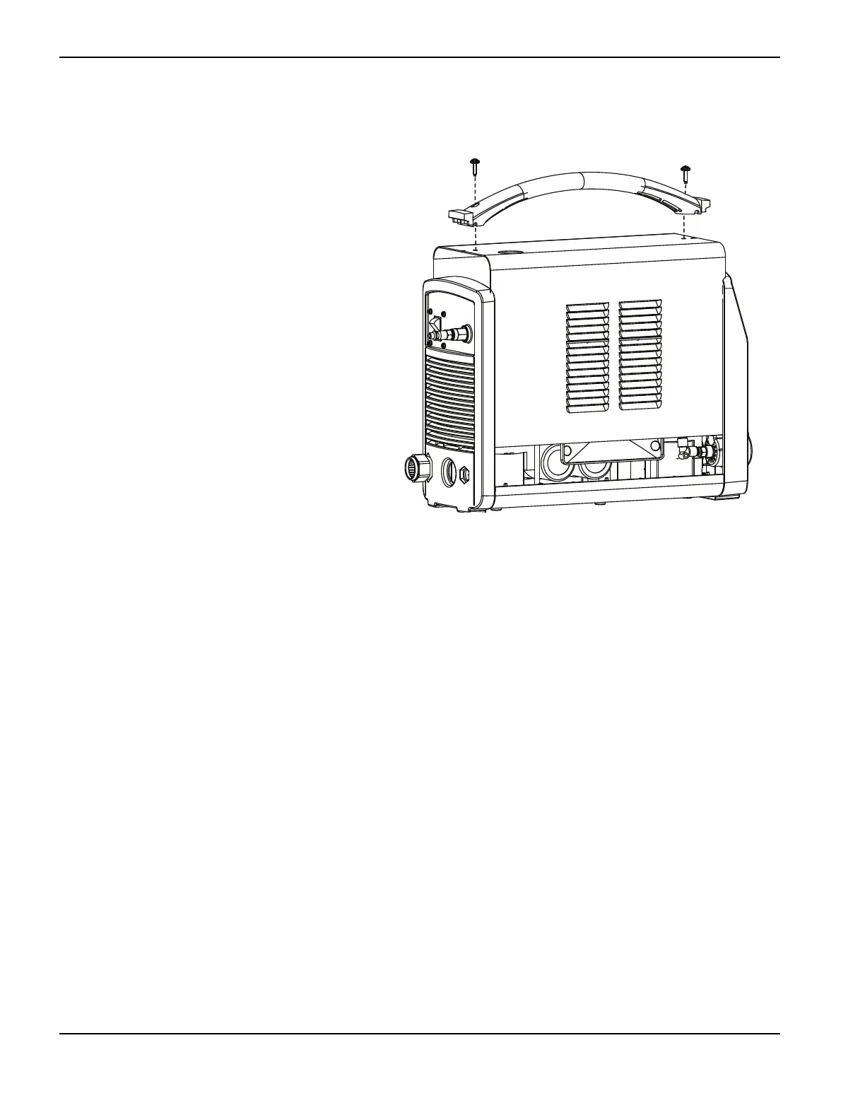
2. Remove the 2 screws from the handle on the
top of the power supply, as shown in Figure 1.
Gently pull on the end panel nearest the screw
you are removing to keep pressure on the
screw. When the screw is almost out, tilt the
screwdriver slightly to help pull the screw out
of the recessed hole.
3. Tip the end panels back slightly so that you
can get the edges of the handle out from
underneath them. Set the handle and screws
aside. Continue to tilt the end panels outward
to release the fan side of the cover from its
track. Then lift the cover off the power supply.
4. Remove the component barrier from the
power-board side of the power supply. The
component barrier is flexible and can be bent
slightly for removal.
If your power supply is a 200–240 V CSA or a
230
V CE model, continue with the following
procedure.
If your power supply is a 400 V CE or a 480 V CSA model, proceed to page 5 for further instructions.
Remove the power board (200–240 V CSA and 230 V CE)
The following procedure applies to 200–240 V CSA and 230 V CE power boards. Please refer to Figure 2 on page 3
and Figure 3 on page 4 when performing this procedure.
1. Detach the ribbon cable from J7 on the heat sink side of the power board.
2. Remove the connectors at J10, J12, and J22 on the heat sink side of the power board.
3. Remove the connectors at J3, J4, and J5 on the heat sink side of the power board.
4. Remove the connector for the red and black wires from the power switch at J6 from the heat sink side of the power
board. J6 is located about an inch down from the top edge of the board.
5. Remove the wires for the transformers and inductors at J13, J14, J15, J16, J17, J18, J19, and J20.
6. Remove the work lead ring terminal from J21 and the 4 capacitor screws.
7. Remove the 3 retaining screws, the 4 heat sink assembly screws, and the 4 snubber resistor screws.
8. If you have an older 200–240 V CSA or 230 V CE power board that has 2 input bridge diodes (and without the
small slot below the heat sink assembly screw hole), remove the 3 screws that attach the IGBTs and the 2 screws
that attach the input bridge diodes to the heat sink. There are holes in the power board to provide access to them.
If you have a newer 200–240 V CSA or 230 V CE power board that has a single input bridge diode (and has a
small slot below the heat sink assembly screw hole), remove the 3 screws that attach the IGBTs and the screw that
attaches the input bridge diode to the heat sink. There are holes in the power board to provide access to them.
Figure 1 – Removing the screws from the handle
 Loading...


