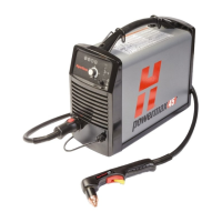
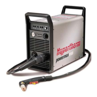
Powermax45/45 XP Field Service Bulletin 807990 7
Powermax45/45 XP Snubber Resistor Replacement Kit
Replace the snubber resistors
Refer to Figure 6 on page 8 when performing the following procedure.
1. Remove both snubber resistors from the heat sink. Each resistor has 2 mounting screws. Discard both of the
snubber resistors.
2. Clean the area on the heat sink where the snubber resistors were mounted. Use isopropyl alcohol to remove the old
thermal grease.
3. Evenly apply a thin coat of thermal grease (3 mm, approximately the thickness of a sheet of paper) to the new
snubber resistor mounting surface. Use the thermal grease included in the kit (128836).
4. Attach the 2 new snubber resistors (109670) to the heat sink using the mounting screws supplied in the kit
(075526). Orient each resistor properly, as shown in Figure 6. Tighten all screws to 23.0 kg cm (20 inch-pounds).
5. Clean the heat sink with isopropyl alcohol. Gently scrub away any excess grease, being careful not to scratch the
heat sink. Wipe it with a clean cloth.
If your power supply is a 200–240 V CSA or a 230 V CE model, proceed to page 9 for further instructions.
If your power supply is a 400 V CE or a 480 V CSA model, proceed to page 10 for further instructions.

 Loading...


