Powermax45/45 XP Field Service Bulletin 807990 5
Powermax45/45 XP Snubber Resistor Replacement Kit
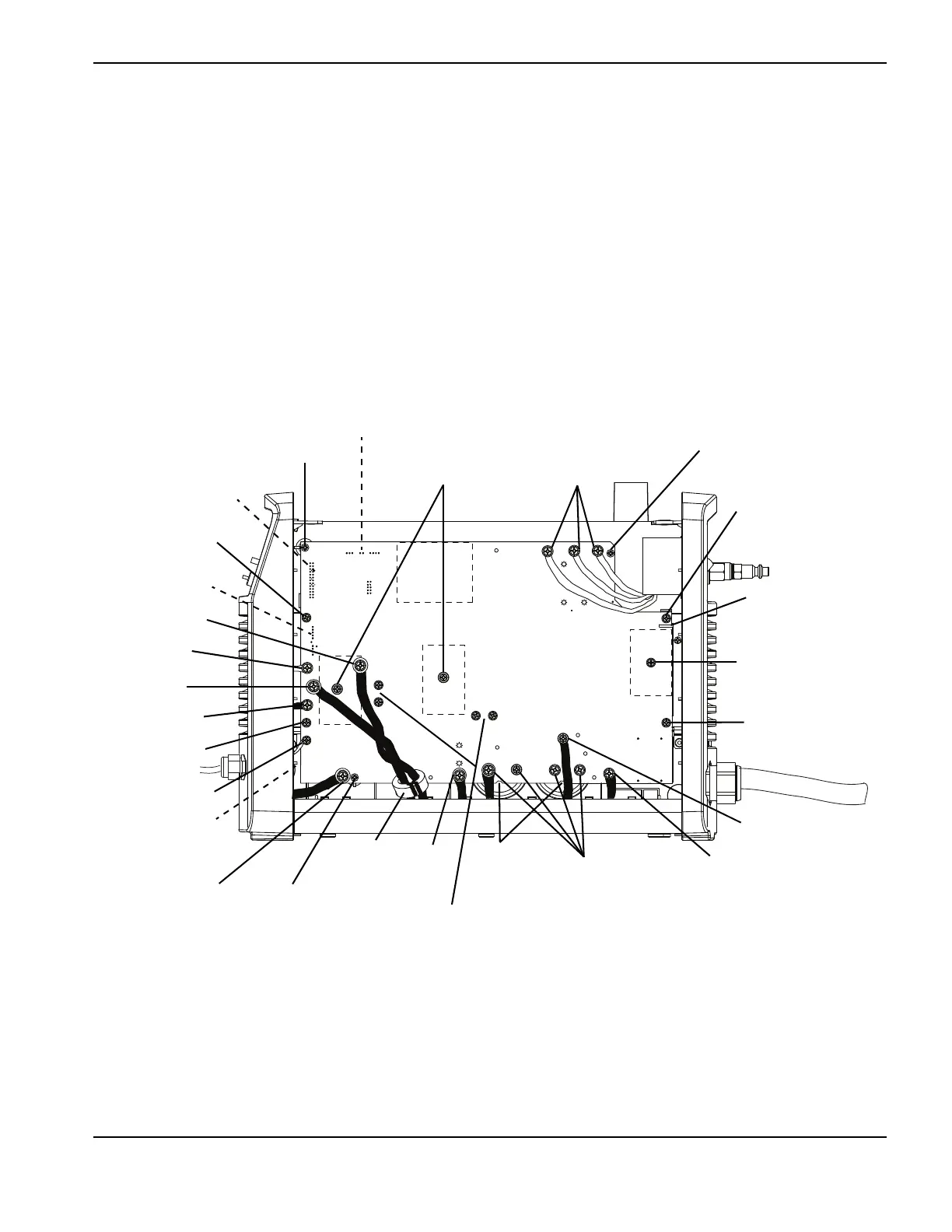
Remove the power board (400 V CE and 480 V CSA)
The following procedure applies to 400 V CE and 480 V CSA power boards. Please refer to Figure 4 on page 5 and
Figure 5 on page 6 when performing this procedure.
1. Detach the ribbon cable from J8 on the heat sink side of the power board.
2. Remove the connectors at J10, J12, and J22 on the heat sink side of the power board.
3. Remove the connectors at J4, J5, and J6 on the heat sink side of the power board.
4. Remove the wires for the transformers and inductors at J13, J14, J15, J16, J17, J18, J19, and J20.
5. Remove the work lead ring terminal from J21 and the 4 capacitor screws.
6. Remove the 3 retaining screws, the 4 snubber resistor screws, and the 4 heat sink assembly screws.
Figure 4 – Newer 400 V CE and 480 V CSA power board
TP17
W
+
-
+
-
TP18
B
TP16
R
~280 VDC
~280 VDC
Heat sink assembly
screw
Ribbon cable (J8)
J10, J12
J13
J14
J15
J16
J18
J22
Heat sink
assembly screw
J4, J5, J6
Retaining screw
IGBT attachment
screws (2)
ON/OFF
switch wires
Retaining screw
Heat sink assembly
screw
Newer boards have a
slot here
J17
Heat sink assembly
screw
Input bridge diode
screw
J3 J2 J1
J19
J20
Retaining
screw
Work lead
connector (J21)
Snubber resistor screws (4)
Pressure relief
vents
Capacitor
screws (4)
Ferrite
(CE units only)
 Loading...


