Machine Interface Receptacle with Voltage Divider PCB
10 806980 Field Service Bulletin Powermax65/85/105/125, Powermax65/85/105 SYNC
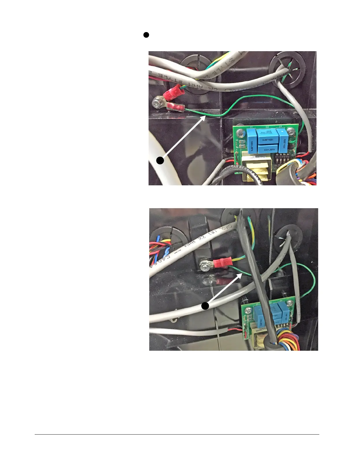
11 . Attach the green ground wire from the voltage divider PCB to the middle panel. Use the
screw that is in the middle panel.
Powermax65/85 and
Powermax65/85 SYNC:
a. Install the ground wire
above the voltage divider
PCB and behind the
other cables, as shown.
b. Do you have the serial
interface port installed? If
you do, attach the green
and yellow ground wire
from the RS-485 serial
interface PCB to the
middle panel with the
same screw.
c. Torque the screw to
1.7 N·m (15 in·lb).
Powermax105/125 and
Powermax105 SYNC:
a. Remove the nut and
washer from the screw.
Use a 7 mm wrench.
b. Install the ground wire
above the voltage divider
PCB and behind the
other cables, as shown.
c. Do you have the serial
interface port installed? If
you do, attach the green
and yellow ground wire
from the RS-485 serial
interface PCB to the
middle panel with the
same screw.
d. Install the washer.
e. Torque the nut to 1.7 N·m (15 in·lb).

 Loading...