Machine Interface Receptacle with Voltage Divider PCB
Powermax65/85/105/125, Powermax65/85/105 SYNC Field Service Bulletin 806980 9
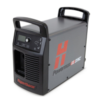
5. Make sure that the green and
yellow ground wire is at
the bottom of the machine
interface receptacle.
6. From the inside of the rear
panel, install the machine
interface receptacle in the
opening.
7. Install 2 screws (075534) in
opposite corners of the
machine interface receptacle,
as shown.
Torque the screws to 1.1 N·m
(10 in·lb).
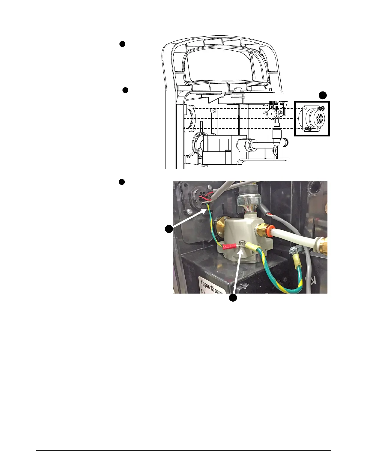
8. Remove the screw that
attaches the green and
yellow ground wire from the
middle panel to the air filter.
9. Attach the green and yellow
ground wire from the machine
interface receptacle to the air
filter with the screw that you
removed in step 8.
Torque the screw to 1.7 N·m
(15 in·lb).
10. Make sure that the green and
yellow ground wire from the
middle panel is also attached
to the air filter with the screw
that you removed in step 8.

 Loading...