EasyManuals Logo
Home>Hypertherm>Welding System>powermax65

Hypertherm powermax65 Field Service Bulletin

Hypertherm powermax65
40 pages
To Next Page IconTo Next Page
To Previous Page IconTo Previous Page
Page #8 background imageLoading...
Page #8 background image
Machine Interface Receptacle with Voltage Divider PCB
8 806980 Field Service Bulletin Powermax65/85/105/125, Powermax65/85/105 SYNC
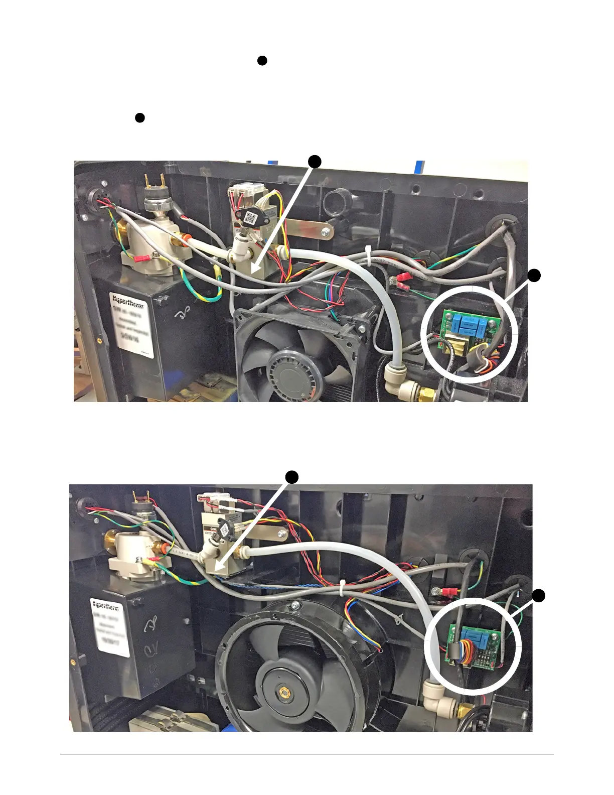
3. Attach the voltage divider PCB to the right of the fan with 2 screws (075534).
Torque the screws to 1.1 N·m (10 in·lb).
4. Make sure that the cables attached to the voltage divider PCB are installed below the solenoid
valve .
Powermax65/85 and Powermax65/85 SYNC
Powermax105/125 and Powermax105 SYNC
1
2
2
1
2
1

Table of Contents

Other manuals for Hypertherm powermax65

Questions and Answers:

Question and Answer IconNeed help?

Do you have a question about the Hypertherm powermax65 and is the answer not in the manual?

Hypertherm powermax65 Specifications

General IconGeneral
BrandHypertherm
Modelpowermax65
CategoryWelding System
LanguageEnglish

Related product manuals