3-3
STARTUP AND COMMISSIONING
DC SERIES BOILERS / WATER HEATERS DC 15-95, DC 15-96, DC 20-125, DC 33-160
The gas valve will automatically de-rate the maximum input in accordance with
the density altitude, by approximately 2% per 1,000' above sea level. The gas
valve’s zero governor will ensure that the gas:air mixture is not be affected at
altitude.
To verify the proper operation of the gas valve in the eld, the following procedure
can be carried out by a qualied technician (diagrams on this page).
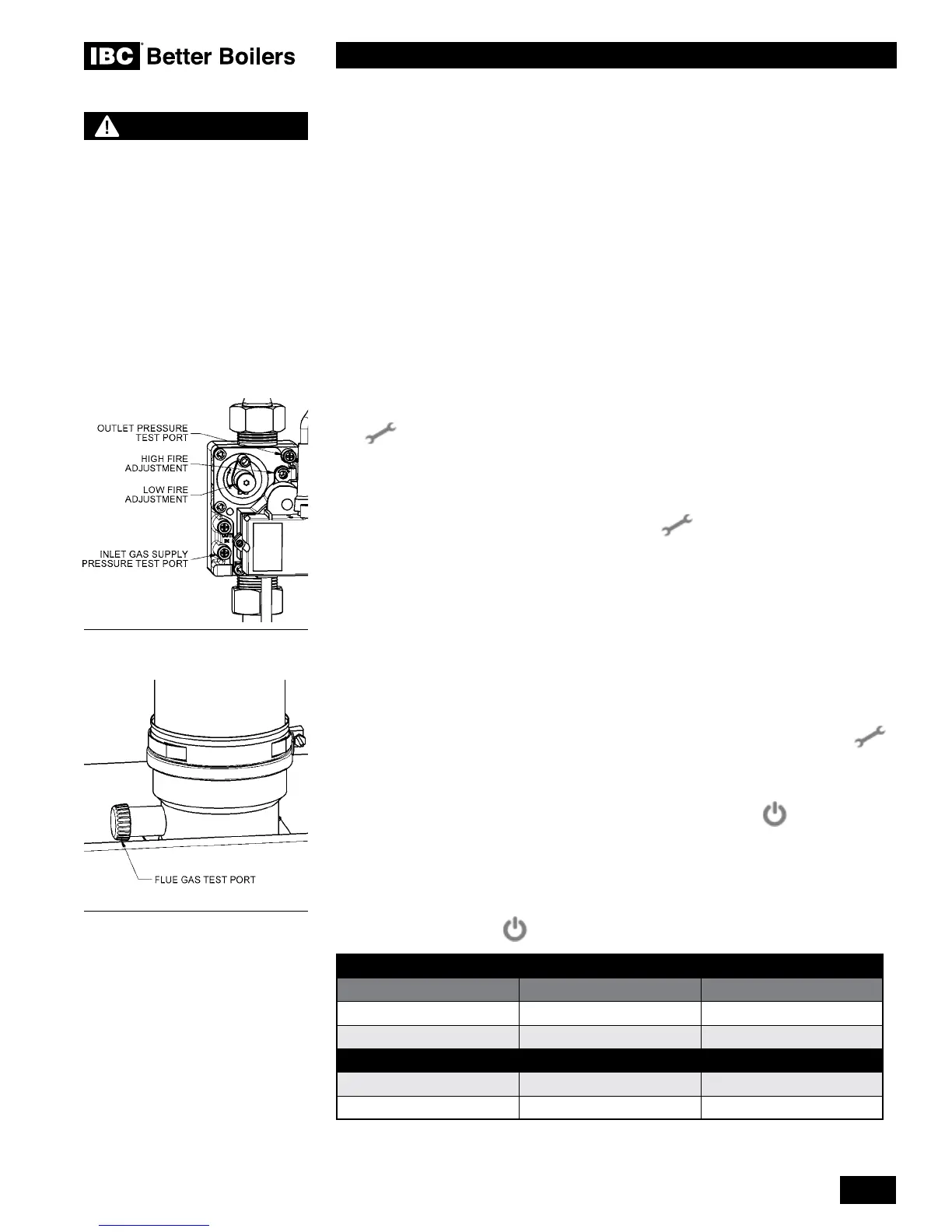
1. Turn off the boiler’s gas shut off valve. With a small (1/8" or 3 mm) at
screwdriver, open the inlet gas supply pressure test port by turning its
center-screw 1 full turn counterclockwise. Attach a manometer to the
pressure test port and turn on gas to appliance. Static manometer reading
should be ideally 7" w.c., for Natural Gas and 11" w.c. for Propane. Minimum
and maximum static pressure should be between 7" and 14" w.c. Monitor
pressure throughout the commissioning procedure. Pressure may droop up
to 1" to 2" w.c. at high re.
2. Allow the boiler / water heater to ignite / run against a large load, to maintain
high re. Enter the High Fire Manual Mode by pressing both the Service
and Plus
+
buttons together twice. “H” will be showing in the service
display. NOTE: Do not make any adjustments if an “h” is showing in the
service display. Allow the boiler / water heater to operate at High Fire for 3
minutes to stabilize. (The boiler / water heater will operate in manual mode
for 10 minutes then switch back to the normal operating mode. To extend
manual mode operation, press the Service and Plus
+
together twice
while the boiler / water heater is operating in manual mode to reset the timer
for 10 more minutes.) Pressing and holding
+
for more than 2 seconds while
in the Service Mode will display the Flame Current in DC microamps. Expect
approximately 9.8μA at High Fire (6.5μA or higher at Low Fire).
3. With a combustion analyzer probe in the ue gas test port, turn the High Fire
(Gas : Air Ratio Adjustment) screw (see diagrams on this page) to achieve
results. This screw offers very ne adjustment, and may require several
turns. Clockwise richens, i.e. raises the CO
2
value.
NOTE: Clock the gas meter to conrm full maximum rating plate input. Check
the measured results with Table 11 - High Fire.
4. Switch the boiler / water heater to low re by pressing both the Service
button and Minus
-
buttons at the same time. The boiler / water heater
will drop to low re. “L” will be showing in the service display. Compare the
readings with Table 11 - Low Fire.
5. Switch off the boiler / water heater by pressing the On/Off button. Turn
off the gas at the boiler / water heater gas shut off valve. Remove the ue
gas analyzer from the test port and reinstall the test port cap. Remove the
gas pressure manometer from the gas valve and close the test port. Turn on
the gas at the boiler / water heater’s gas shut off valve. Ensure there are no
gas leaks and reinstall the front cover. Turn on the boiler / water heater by
pressing the On/Off button.
CO
2
VALUE (%) AT HIGH FIRE WITH THE FRONT COVER OPEN
NATURAL GAS PROPANE
Max. CO
2
value 10.1% 11.5%
Min. CO
2
value 9.1% 9.8%
CO
2
VALUE (%) AT LOW FIRE WITH THE FRONT COVER OPEN
Max. CO
2
value = value at High = value at High – 0.3%
Min. CO
2
value 9.1% 9.5%
Table 11: CO
2
Values and High and Low Fire
Gas Valve Adjust
Flue gas test port plug
WARNING
Check the rating plate of the
boiler / water heater to ensure
it is congured for the fuel
you are using. If the fuel is
incorrect for the appliance,
a conversion kit must be
ordered from IBC and the gas
valve adjusted accordingly.
Failure to perform the
required fuel conversion can
result in an immediate hazard.
 Loading...


