1-1
INSTALLATION
DC SERIES BOILERS / WATER HEATERS DC 15-95, DC 15-96, DC 20-125, DC 33-160
INSTALLATION1.0
GENERAL
DC Series gas-red modulating boilers / water heaters are low pressure, fully
condensing units having variable input ranges (see specication chart - page 3).
The boilers / water heaters are approved as “Category IV” vented appliances
using Direct Vent (sealed combustion).
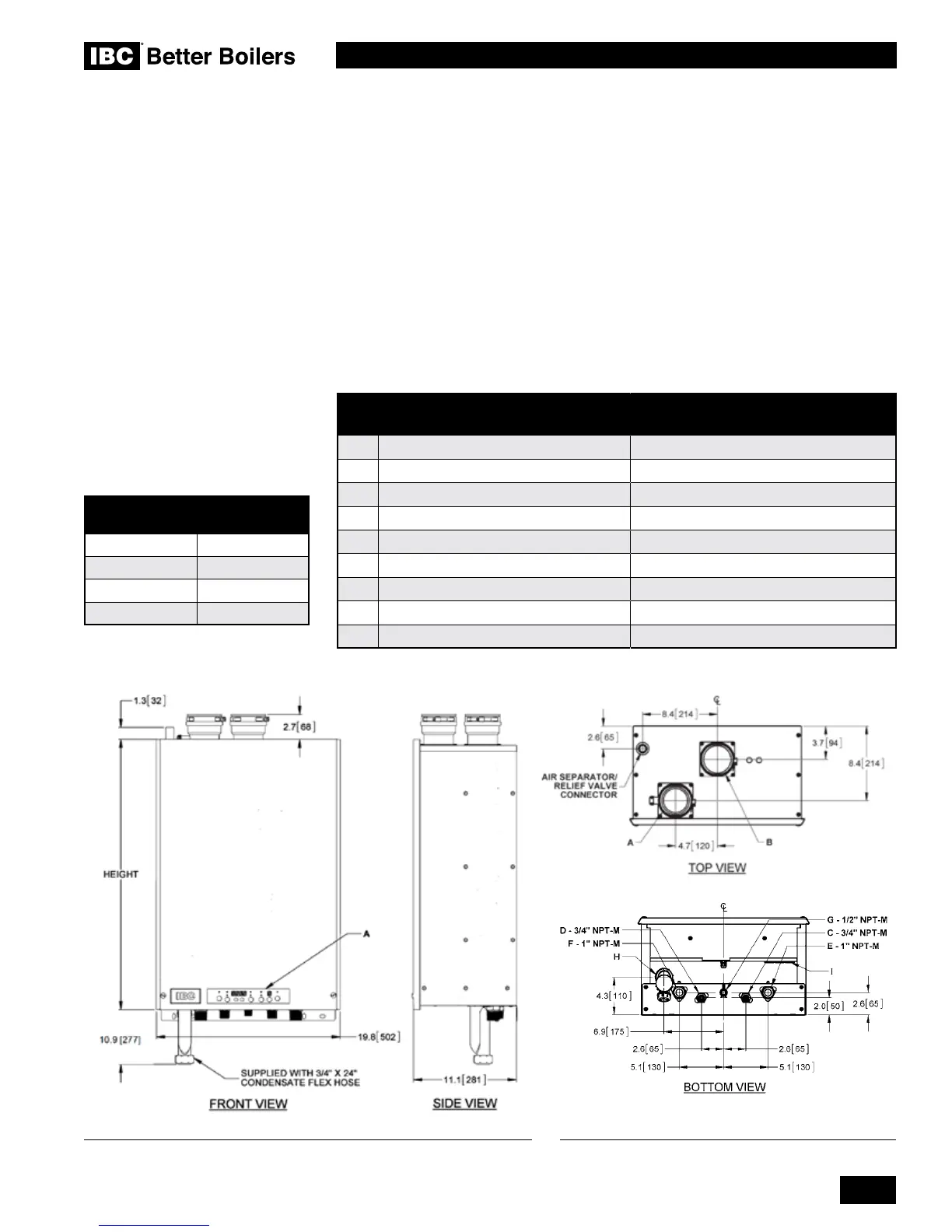
Figure 1 shows outer case dimensions and piping and electrical holes. Use this
diagram to nd a suitable location for the boiler / water heater. See also Section
1.3 Location.
DESCRIPTION
DC SERIES BOILERS / WATER
HEATERS
A Exhaust Outlet 3" Schedule 40
B Combustion Air 3" Schedule 40
C
Cold Domestic Water Connection
3/4" Male NPT
D Hot Domestic Water Connection 3/4" Male NPT
E Heating Water Inlet (Return) 1" Male NPT
F Heating Water Outlet (Supply) 1" Male NPT
G Gas Inlet 1/2" Male NPT
H Condensate Outlet 3/4" Hose
I Knock-out (3) 1/2"
Table 1: Connections
1.1
Figure 1a: Dimensions / Connections for DC Series Figure 1b: Dimensions / Connections for DC Series
MODEL
NUMBER
HEIGHT
DC 15-95 29.0" [736]
DC 15-96 31.3" [796]
DC 20-125 31.3" [796]
DC 33-160 31.3" [796]
 Loading...


