7.
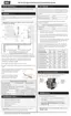
Remove the screws from the outlet side of the gas valve (see on Figure 51 ) to separate the
gas valve from the appliance. To do this, ensure that you support the bottom of the gas valve
when you remove the bottom two (2) screws (see Figure 57 ) and then the top two (2) screws.
Figure 57 Gas valve outlet screws
8.
Replace with the new gas valve following the steps in reverse order. Upon reassembly, ensure
that all O-rings are well seated in their grooves.
Tip: Lightly hand-tighten each screw before tightening all four screws fully on both the
outlet and inlet sides of the gas valve. To prevent gas leaks, ensure that the O-rings on
the outlet side and inlet side are well seated in their grooves.
9. Tune the gas valve. For instructions, see Adjusting the gas valve (EX 400, EX 500) on page
74.
10. Turn on the electric power and gas supply to the boiler.
11. Reset the low pressure switch. For instructions, see Resetting the gas high / low pressure
switches on page 77.
7.2.2 Replacing the gas valve in the EX 400 and EX 500 models