6.8.4 Thermostat wiring
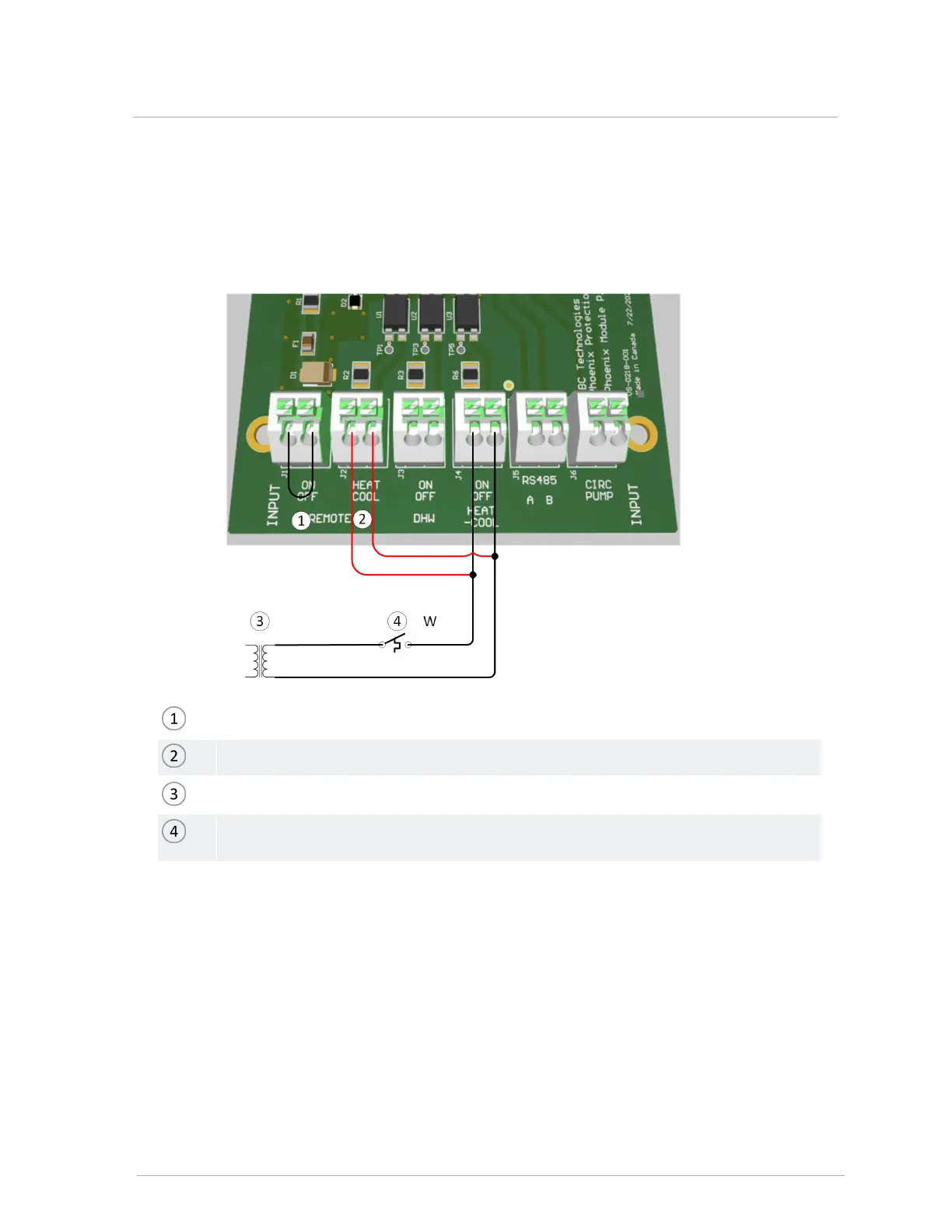
Thermostat-type control wiring will go to the J4 terminals (On Off Heat Cool). To make the control
signal a call for heating (no cooling), wire the J2 (HeatCool) and J4 (On Off Heat Cool) terminals in
parallel as shown.
Jumper between J1 terminals (interlock)
Pigtail to HPXJ2 terminals (heating-only mode)
24V Transformer
Thermostat wires send a 24V signal to HPXJ4 terminals: W for heating-only thermostat,
Y for heat-pump t-stat.
Figure 17 HPX Series thermostat field wiring
For a load with multiple zones (e.g. thermostats controlling zone valves), use a zone control
module, or wire the end-switches of each zone valve in parallel and send a 24V signal through
them to the J4 terminals on the HPX controller.
Ensure that there are no disturbing influences on the call-for-heat lines. Most power-stealing
thermostats can be connected directly to the HPX Series terminals.
 Loading...