6.8.6 Other wiring
Other optional low voltage connections to the control board include:
An auxiliary Interlock at J1 terminals - for external safety devices as may be required by
some jurisdictions, such as an external low-water cutoff. Shown in Figure above, as
"Remote On/Off."
6.8.7 Buffer tank sensor wiring
IBC recommends the use of a buffer tank to separate the HPX Series operation cycles from the load
operation cycles.
See separate manual IBC Sky 35 Controller for more information.
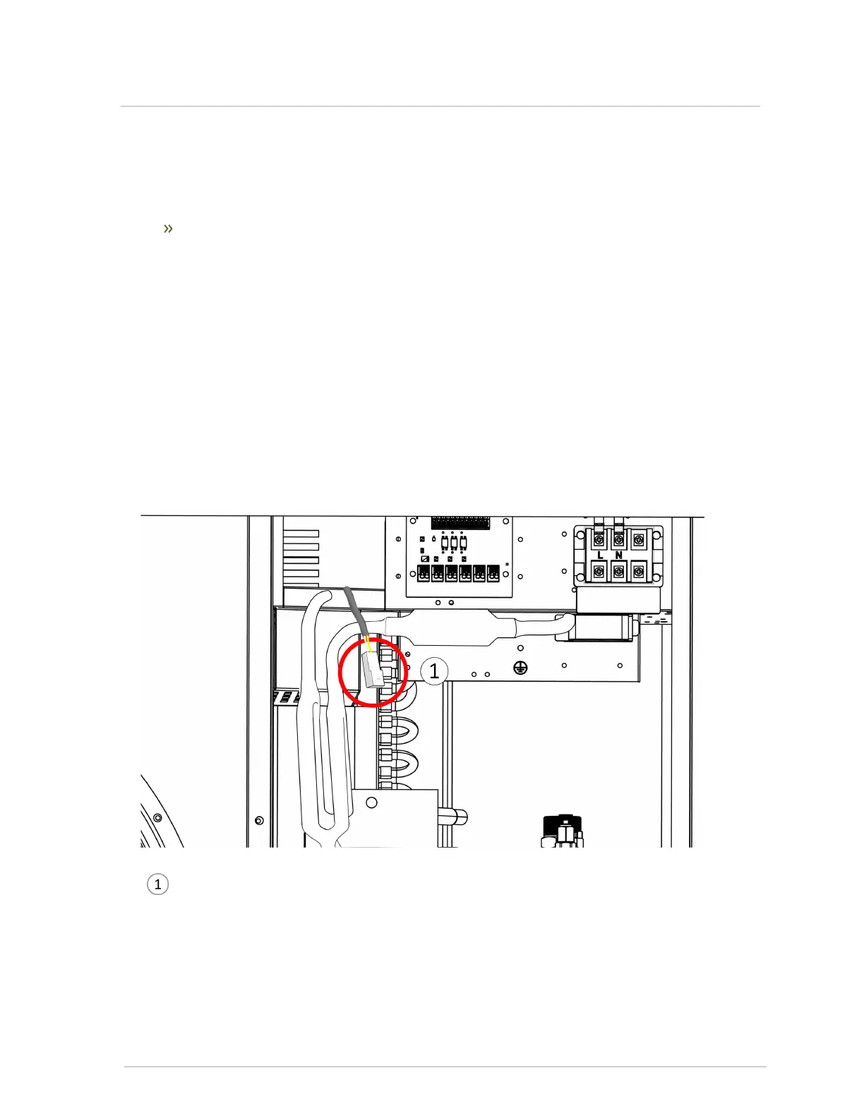
For stand-alone operation, attach the supplied 10KΩ tank sensor to the two-wire quick-connector
near the field-wiring board.
Buffer tank 10KΩ sensor quick connector
Figure 18 HPX Series buffer tank sensor field wiring connection
 Loading...