1-19
INSTALLATION
VFC 15-150 - VFC 45-225 MODULATING GAS BOILERS
WATER PIPING
1.6.1 General Piping Issues
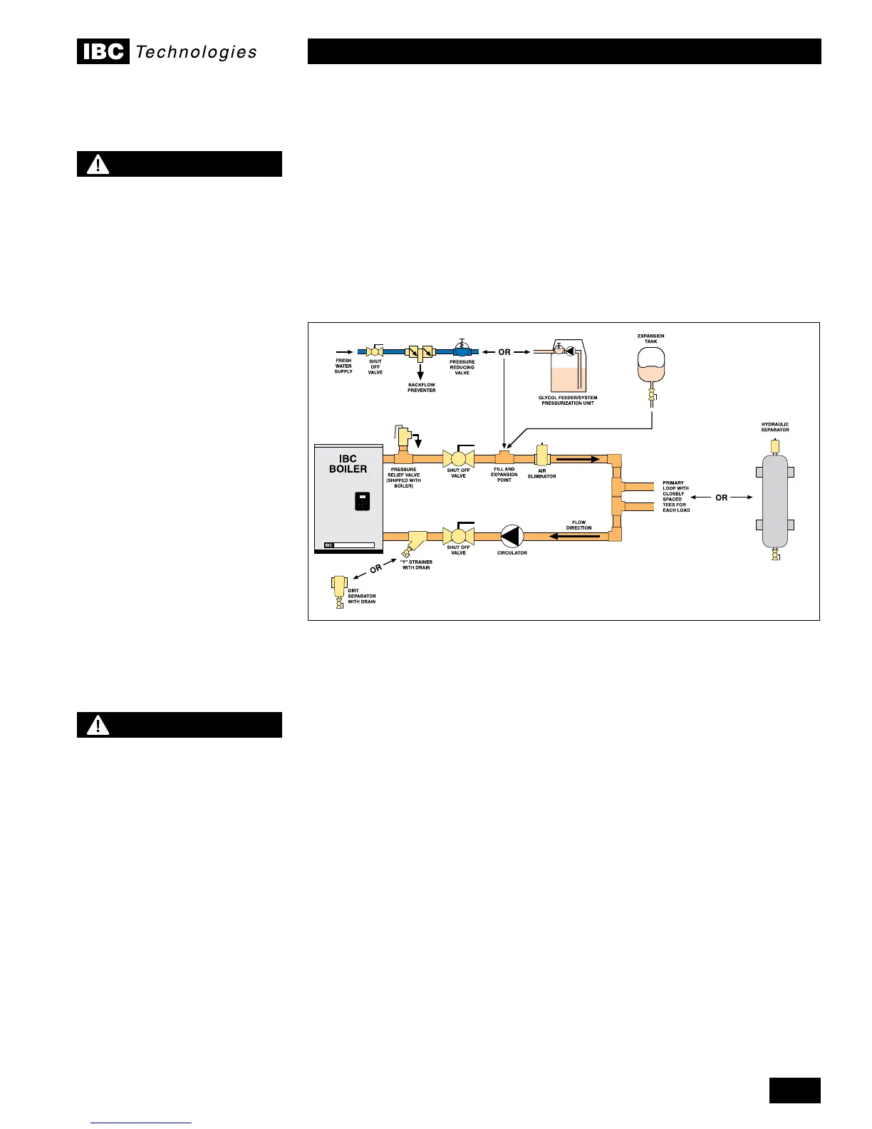
The VFC modulating series boilers are designed for use within a closed loop,
forced circulation, low pressure system. A 30 psi pressure relief valve (3/4" NPT)
issuppliedforeldinstallationintheowsupplyline–seebelow.Anoptional75
Psig relief valve can be used where required on closed loop systems within multi-
level buildings. Relief valve discharge piping must terminate between 6" (15cm)
and12”(30cm)abovetheoorusingplainun-threadedend,orperlocalCode.
Systempipingisconnectedtotheboilerusingthe1-1/4"NPT-Mthreadedttings.
Unions and gate or ball valves at the boilers supply and return water connections
are recommended to simplify servicing. Un-insulated hot water pipes must be
installed with a minimum 1" clearance from combustible materials.
Fluidllismostoftenaccomplishedbyusingaboilerregulator&llvalveset
at12psigormore,withappropriatebackowpreventiondeviceasrequiredby
local code. This is acceptable in areas where municipal water or well water has
beentreatedandlteredtoremoveexcessivemineralsandsediment,andwater
chemistry is known to be suitable for closed loop hydronic systems. In areas where
water quality is in question, or when chemical treatment or glycol is required, other
options should be considered. Follow applicable Codes and good piping practice.
There are a number of boiler feed and pressurization devices on the market
todaythatmaybeabetterchoicethanarawwaterllfromthemains.When
regular maintenance requires relief valve blow-off, the discharge may be directed
backintothepressurizationunitforrecyclingofboileruidandchemicals
back into the system. In buildings that may be unoccupied for long periods of
time,pressurizationunitsareusefultopreventooddamageshouldleakage
occurfromanycomponentinthesystem.Anadditionalbenetisthatbackow
prevention devices are not required when using these devices.
Figure 21: Boiler trim options
CAUTION
Installers should inquire of
local water purveyors as to
the suitability of their supply
for use in hydronic heating
systems.
If water quality is
questionable, a local water
treatment expert must
be consulted for testing,
assessment and, if required,
treatment.
Alternatively, water or
hydronic uid of known
quality can be brought to the
site.
WARNING
During operation, the relief
valve may discharge large
amounts of steam and/or hot
water. Therefore, to reduce
the potential for bodily
injury and property damage,
a discharge line MUST be
installed that it:
1. is connected from the valve outlet
with no intervening valve and
directed downward to a safe point of
discharge.
2. allows complete drainage of both the
valve and the discharge line.
3. is independently supported and
securely anchored so as to avoid
applied stress on the valve.
4. is as short and straight as possible
5. terminates freely to atmosphere
where any discharge will be clearly
visible and is at no risk of freezing.
6. terminates with a plain end which is
not threaded.
7. is constructed of a material suitable
for exposure to temperatures of
375°F or greater.
8. is, over its entire length, of a pipe size
equal to or greater than that of the
valve outlet.
DO NOT CAP, PLUG OR OTHERWISE
OBSTRUCT THE DISCHARGE PIPE
OUTLET!
1.6
 Loading...


