1-25
BOILER SYSTEMS AND OPERATION
VFC 15-150 - VFC 45-225 MODULATING GAS BOILERS
For further information and details, consult our Application Notes – which provide
detailonspecicsingleandmultipleboilerapplications“Piping”, “Wiring” and
“Settings”. (available at www.ibcboiler.com or from your IBC Representative).
GAS PIPING
The boiler requires an inlet gas pressure of at least 3.0" w.c. for natural gas or
propane. For either fuel, the inlet pressure shall be no greater than 14.0" w.c.
Conrmthispressurerangeisavailablewithyourlocalgassupplier.
The inlet gas connection of the boiler’s gas valve is 1/2" NPT (female).
Adequate gas supply piping shall be provided with no smaller than 1/2" Iron Pipe
Size (IPS), in accordance with the following chart:
MODEL 1/2" IPS 3/4" IPS 1" IPS
VFC 15-150 (Natural Gas) 10 40 130
VFC 15-150 (Propane) 50 180 620
VFC 45-225 (Natural Gas) 5 20 60
VFC 45-225 (Propane) 25 90 290
Table 7: Maximum Pipe Length (ft)
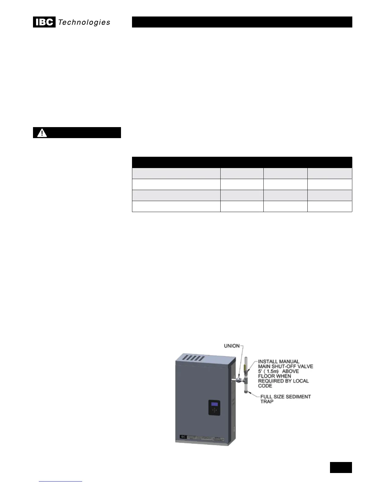
Gas piping must have a sediment trap ahead of the boiler’s gas valve (see Figure
28). A manual shutoff valve must be located outside the boiler, in accordance with
local codes/standards. All threaded joints in gas piping should be made with an
approved piping compound resistant to the action of natural gas/propane. Use
proper hangers to support gas supply piping as per applicable codes.
The boiler must be disconnected or otherwise isolated from the gas supply
during any pressure testing of the system at test pressures in excess of 1/2 psig.
Dissipate test pressure prior to reconnecting. The boiler and its gas piping shall
be leak tested before being placed into operation.
The gas valve is provided with pressure taps to measure gas pressure upstream
(supply pressure) and downstream (manifold pressure) of the gas valve (see
Figure 31).Notethatmanifoldpressurevariesslightlyinaccordancewithring
rates with the modulating series boilers, but will always be close to 0” w.c.
1.7
Figure 28: Typical gas piping
NOTE
Due to the precision of
modern modulating boilers
it is important to pay special
attention to gas pressure
regulation.
It is essential to check gas
supply pressure to each
boiler with a manometer or
other high-quality precision
measuring device. Pressure
should be monitored before
ring the boiler, when the
regulator is in a “lock-
up” condition and during
operation, throughout the
boiler’s full modulation range.
Pay special attention to
retrot situations where
existing regulators may have
an over-sized orice and/or
worn seats, causing pressure
“creep” and high lock up
pressures.
A high quality regulator will
maintain constant pressure
above the boiler’s minimum
specication at all ring
rates, and will not exceed the
boiler’s maximum pressure
rating when locked-up with no
load.
 Loading...


