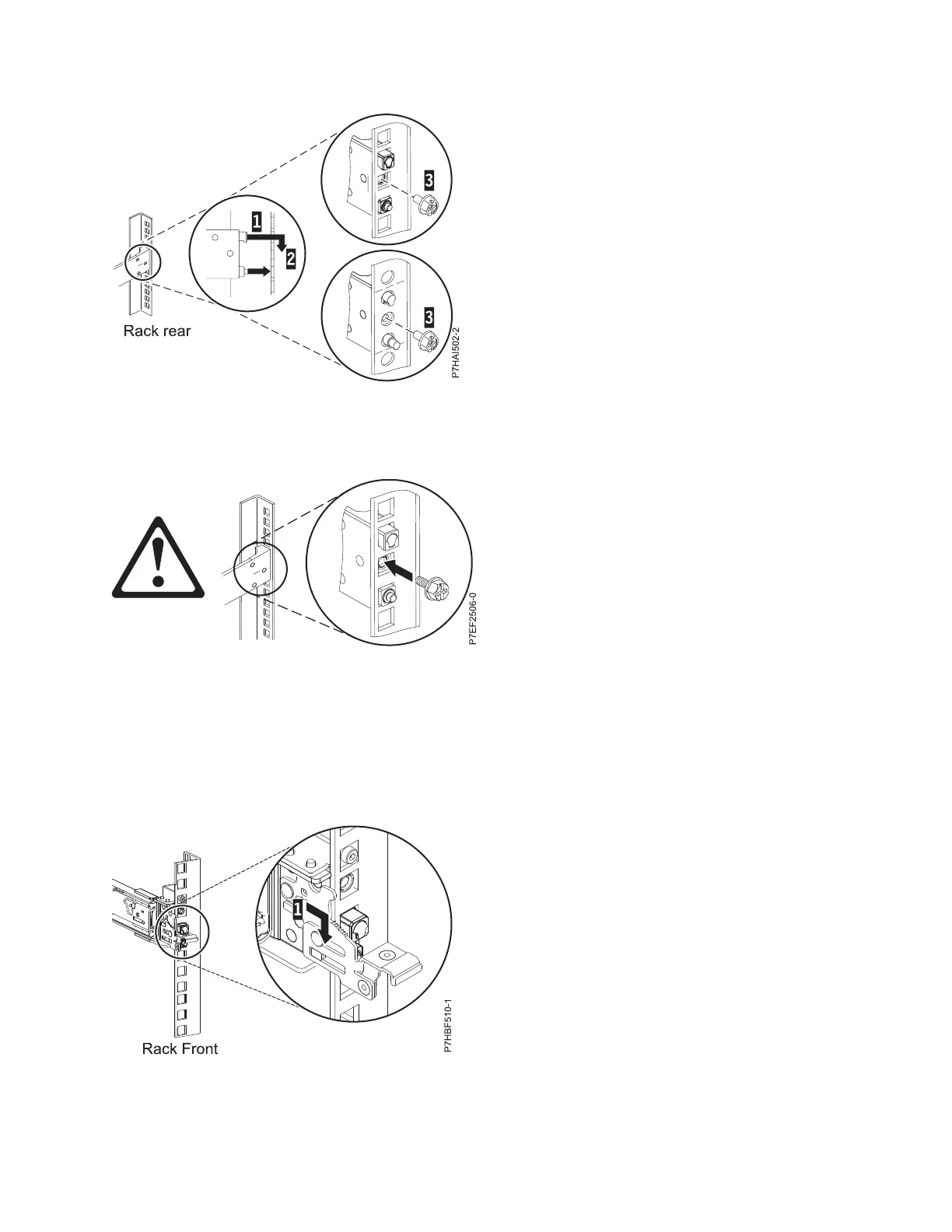
4. Reinstall the screw that was removed in step 2 on page 4, as shown in Figure 4.
5. Return to the front of the rack. Ensure that the latch is still open on the front of the slide rail. Refer to
step 2 on page 4.
6. Pull the slide rail forward and insert three pins on the front of the rail into the holes within the
selected EIA unit that were previously marked. Lower the slide rail down (1) to engage the hook
feature on the middle pin. For details, see Figure 5.
Figure 3. Aligning and engaging the pins into the holes in the rear of the rack
Figure 4. Reinstalling the screw
Figure 5. Pins that are seated on the front rail of the rack
Installing the IBM Power System S814 (8286-41A) 5
 Loading...