4 - 1
SECTION 4 CIRCUIT DESCRIPTION
4-1 RECEIVER CIRCUITS
4-1-1 TRIPLEXER AND RX BAND SWITCHING
CIRCUITS (MAIN UNIT)
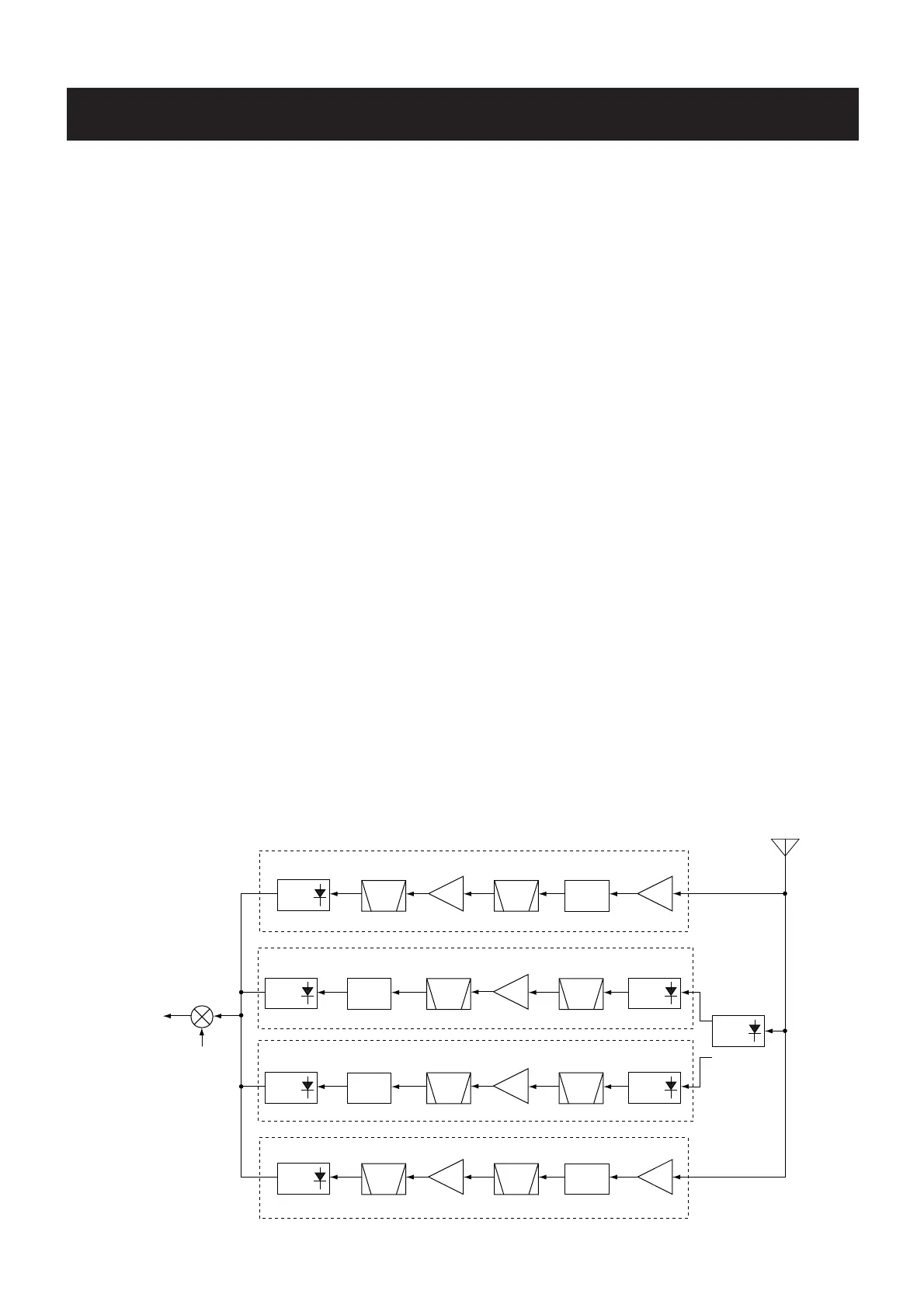
The transceiver has a triplexer (low-pass and high-pass fil-
ters) on the first stage from the antenna connector to sepa-
rate the signals into VHF and UHF signals. The RF signals
from the antenna connector are applied to the tripler or RX
band swtich circuits.
• RF SIGNALS V-V (118 MHz–180 MHz), U-V (136
MHz–174 MHz)
The V-V and U-V RF signals from the antenna connector
pass through the low-pass filter (L76, L77, L80, C205, C209,
C242, C243, C264), and then applied to the TX/RX switching
circuit (D42, D46, D52, D67, D2049). The filtered signals are
amplified at the pre-amplifier (Q33), and are applied to the
left side or right side displayed RX circuits.
• RF SIGNALS U-U, V-U2 (375 MHz–550 MHz)
The U-U and V-U2 RF signals from the antenna connector
pass through the high-pass filter (L78, L81, C206, C210,
C213, C265), and then applied to the TX/RX switching circuit
(D55, D64, D65, D2050) via the SWR detector (D50, D58).
The filtered signals are amplified at the pre-amplifier (Q24),
and are applied to the left side or right side displayed RX cir-
cuits.
• RF SIGNALS U-U3 (810 MHz–1000 MHz)
The U-U3 RF signals from the antenna connector pass
through the two low-pass filters (L76, L77, L80, C205, C209,
C242, C243, C264, L87, L88, C266–C268), and are then
applied to the RX band swtiching circuit (D2061). The filtered
signals are amplified at the RF amplifier (Q18), and are
applied to the right side displayed RX circuits.
• RF SIGNALS V220 (174 MHz–260 MHz), V-U1 (225
MHz–375 MHz)
The V220 and V-U1 RF signals from the antenna connector
are applied to the RX band swtiching circuit (Q34, D66, RL1),
and are applied to the left side displayed RX circuit.
4-1-2 RF CIRCUIT FOR LEFT SIDE DISPLAY
(MAIN UNIT)
• RF SIGNALS V-V (118 MHz–180 MHz)
The amplified signals are applied to the RF amplifier (Q29)
after being passed through the attenuator (D59) and band-
pass filter (D47, D53). The signals are applied to the RX
band switching circuit (D28) via the another bandpass filter
(D32, D39) to supress the unwanted signals.
• RF SIGNALS V220 (174 MHz–260 MHz)
The signals are applied to the RF amplifier (Q31) after being
passed through the RX band switching circuit (D62) and
bandpass filter (D51). The amplified signals are applied to
the RX band switching circuit (D28) via the another bandpass
filter (D34) to supress the unwanted signals and attenuator
(R195–R197).
• RF SIGNALS V-U1 (225 MHz–375 MHz)
The signals are applied to the RF amplifier (Q32) after being
passed through the RX band switching circuit (D63) and
bandpass filter (D49). The amplified signals are applied to
the RX band switching circuit (D31) via the attenuator
(R198–R200) and another bandpass filter (D35) to supress
the unwanted signals.
• RF SIGNALS V-U2 (375 MHz–550 MHz)
The amplified signals are applied to the RF amplifier (Q20)
after being passed through the attenuator (D25) and band-
pass filter (D23, D73). The signals are applied to the RX
band switching circuit (D9) via the another bandpass filter
(D13, D17) to supress the unwanted signals.
 Loading...