3 - 11
85
86
88
89
90
91
92
93
94
95
96
97
99
Outputs the communicating signal with
the main unit.
Input port for the sub-dial’s B phase
signal.
Input port for [P.AMP/ATT] and
[TUNER/CALL] keys.
Input port for [MENU] and [F-1] keys.
Input port for [F-2] and [F-3] keys.
Input port for [DISPLAY] and [LOCK]
keys.
Input port for [MODE] and [TS] keys.
Input port for [BAND UP] and
[BAND DN] keys.
Input port for the microphone PTT sig-
nal.
Input port for the microphone
UP/DOWN signal.
Input port for the AF volume control
signal.
Input port for the RS/SQL volume con-
trol signal.
input port for the SHIFT volume control
signal.
LTXD
SDBK
PRAK/
TUNK
MENK/
F1K
F2K/F3K
DISK/
LCKK
MODK/
TSK
BUPK/
BDNK
PTTL
FUDL
AFGL
SQLL
SFTL
(DISPLAY BOARD; IC6)–Continued
Pin Port
Description
number name
2
3
4
5
6
7
8
16
17
18
19
20
21
22
24
25
26
29
30
31
39–42
44–50
51–82
83
84
Output key backlight control signals.
Input port for the phone plug insert
detecting signal.
High : While the phone plug is insert-
ed.
Input port for the [RIT/SUB] key.
Input port for the main dial’s A phase
signal.
Input port for the main dial’s B phase
signal.
Input port for the sub dial’s A phase
signal.
Outputs the “P.AMP” LED control sig-
nal.
Outputs the “ATT” LED control signal.
Outputs the “TUNER” LED control sig-
nal.
Outputs the “RIT” LED control signal.
Outputs the “LOCK” LED control sig-
nal.
Outputs the “RX” LED control signal.
Outputs the “TX” LED control signal.
Output the LCD backlight control sig-
nals.
Outputs sub-dial’s LED control signal.
Output the LCD driver (IC2) control
signals.
Output LCD common signals.
I/O port for LCD driver’s data signals.
Output LCD segment signals.
Outputs the LCD driver reset signal.
Low : While the LCD driver is reset.
Input port for the communicating sig-
nal with the main unit.
3-6-2 SUB CPU PORT ALLOCATIONS
(DISPLAY BOARD; IC6)
KL1S
KL2S
PHNK
RSK
MDAK
MDBK
SDAK
PRED
ATTD
TUND
RITD
LCKD
RXD
TXD
BL1S
BL2S
SUBD
WR
RD
A0
COM4–
COM1
DB7–
DB0
SEG1–
SEG32
LRES
LRXD
Pin Port
Description
number name
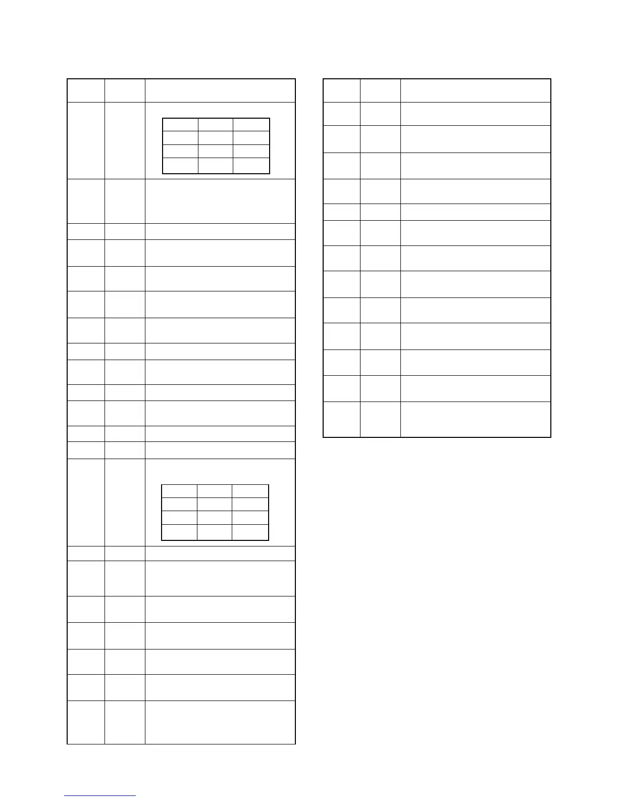
KL1S KL2S Lights
Low Low OFF
High Low Low
High High High
BL1S BL2S Lights
Low Low OFF
High Low Low
High High High

 Loading...