3 -
31ST
LOCAL OSCILLATOR CIRCUITS
The 1st local oscillator employs a premix system consist-
ing
of a PLL and a crystal oscillator for each band.
1. PLL
(PHASE LOCKED LOOP) CIRCUITS
The PLL employs a mixed down type, and
is
locked
in
10kHz steps. This
output
is
divided into
1/10,
as a result,
1 kHz steps
is
obtained.
The local oscillator,
01
oscillates
at
13. 666MHz with
the
crystal unit X2. This signal
is
tripled
at
02
and
03,
thus
the
local oscillator
output,
123MHz
is
obtained. A varactor
diode, 01
is
connected
in
series with X2, and voltages from
the
RIT control and FREOUENCY SET control are applied
to
the cathode and anode respectively. This varies the local
oscillator frequency slightly
to
provide
the
RIT function
and frequency Cillibration.
06
is
the
VCO
(Voltage Controlled Oscillator), and oscil-
lates
at
a frequency between 132MHz and 139MHz. The
Address
Data
Address Data
output
signal
is
fed
to
the
base
of
04,
PLL mixer, through
buffer amplifiers
07
and
08.
To
the
emitter
of
04,
the
local oscillator signal
is
fed and mixed with
the
VCO
signal
to
mix down
the
VCO
frequency.
The
output
signal from the mixer
is
fed
to
the low·pass
filter consisting of C23,
L6
and C24,
to
filter
out
only the
signal below 15MHz. Then the signal
is
amplified
to
the
proper
level
(more than 3V
poP)
of the programmable
divider,
IC1, by
05.
IC1, PLL
IC,
consists
of
the programmable divider,
re-
ference frequency oscillator, fixed divider, phase detector,
etc. The reference frequency oscillator oscillates
at
9.000
MHz,
and its signal
is
divided into 10kHz and fed
to
the
phase detector as
the
reference frequency.
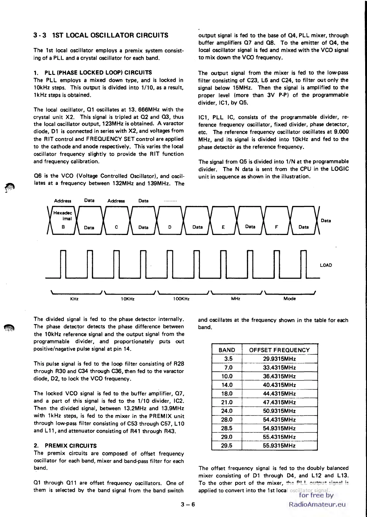
The signal from
05
is
divided into 1 IN
at
the programmable
divider. The N data
is
sent from the
CPU
in
the
LOGIC
unit
in
sequence
as
shown
in
the illustration.
Data
\~
_____
....JI\,,"
______
JI\,,"
______
..JI\~
_____
....JI\
.......
______
J
KHz
10KHz
100KHz
The divided signal
is
fed
to
the phase detector internally.
The phase detector detects the phase difference between
the
10kHz reference signal and
the
output
signal from
the
programmable divider, and proportionately puts
out
positive/nagative pulse signal
at
pin 14.
This pulse signal
is
fed
to
the loop filter consisting
of
R28
through R30 and C34 through C36, then fed
to
the varactor
diode,
02,
to
lock the
VCO
frequency.
The locked
VCO
signal
is
fed
to
the buffer amplifier,
07,
and a part of this signal
is
fed
to
the
1/10
divider, IC2.
Then the divided signal, between 13.2MHz and 13.9MHz
with 1kHz steps,
is
fed
to
the
mixer
in
the PREMIX unit
through low-pass filter consisting
of
C53 through C57, L10
and L 11, and attenuator consisting of
R41
through R43.
2.
PREMIX CIRCUITS
The premix circuits are composed
of
offset frequency
oscillator for each band, mixer and band·pass filter for each
band.
01
through 011 are offset frequency oscillators. One
of
them
is
selected
by
the
band signal from the band switch
3-6
MHz
Mode
and oscillates
at
the frequency shown
in
the table for each
band.
BAND
OFFSET FREOUENCY
--
3.5
29.9315MHz
.-
7.0 33.4315MHz
10.0 36.4315MHz
14.0 40.4315MHz
----
18.0
44.4315MHz
21.0 47.4315MHz
24.0 5O.9315MHz
28.0 54.4315MHz
28.5 54.9315MHz
29.0 55.4315MHz
---
29.5 55.9315MHz
The offset frequency signal
is
fed
to
the doubly balanced
mixer consisting
of
01
through
04,
and L 12 and L 13.
To the other port
of
the mixer, the PLL
output
signal
is
applied
to
convert into the 1 st local oscillator signal.
for
free
by
RadioAmateur.eu

 Loading...


