EasyManuals Logo

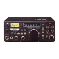
Icom IC-730 Maintenance Manual

Icom IC-730
136 pages
To Next Page IconTo Next Page
To Previous Page IconTo Previous Page
Page #66 background imageLoading...
Page #66 background image
Q)
I
....
w
I
8 - 4 TRANSMITTER ADJUSTMENT
Adjustment
Adjusting procedures
item
SWR
meter
1)
Set
the mode switch
to
CW,
band switch
adjustment
to
14
MH.z
and
meter
to
RF.
2)
Connect
5O-ohms
dummy Load
or
RF
wattmeter
to
the
ANT
connector.
3) Rotate R82
of
MAIN
UNIT
and
RF
POWER
Control
fully
clockwise.
4)
Set
Sl
of
MAIN
UNIT
to
SWR.
5)
Adjust
C31
of
FILTER
PCB
so
that the
meter deflection
becomes
minimum in
transmit mode.
ALC
1)
Set the mode switch
to
CW
and
band
adjustment
switch
to
14 MHz.
2)
Set
Sl
of
MAIN
UNIT
to
RF
POWER
side.
Rotate
RF
POWER
control on the
front
panel
fully
clockwise.
3)
Connect
5O-ohms
wattmeter
to
the
ANT
connector.
4) Set meter switch on the
front
panel
to
ALCside.
5)
Ground the KEY terminal on the
rear
panel.
.
,v.
Measuring location
Adjusting location
Number
of
Instrument
adjusting
Measuring
UNIT
Terminal
UNIT
Parts
reading
location
instruments
5O-ohms
Rear
ANT
dummy
panel
(R82)
3
Load or
RF
(Sl )
wattmeter
FILTER
C31
Minimum
~
meter
deflection.
(Sl ) @
RF
Rear
ANT
wattmeter
panel.
4
.~.
Qi
- I \
:4
for
free
by
RadioAmateur.eu

Other manuals for Icom IC-730

Questions and Answers:

Question and Answer IconNeed help?

Do you have a question about the Icom IC-730 and is the answer not in the manual?

Icom IC-730 Specifications

General IconGeneral
BrandIcom
ModelIC-730
CategoryTransceiver
LanguageEnglish

Related product manuals