SECTION
4
CIRCUIT DESCRIPTION
4-1
RECEIVER CIRCUITS
4-1-1
RF SWITCHING
CIRCUIT
(CTRL
AND RF UNITS)
The RF
switching circuit leads
receive signals
to
bandpass
filters from an
antenna
connector
while
receiving.
While
transmitting, this circuit leads the
signals from the RF power
amplifier to the
antenna connector.
RF signals
from an antenna
connector,
pass through the
antenna
selecting relay (RL3), transmit/receive
switching
relays
(RL1, RL2, RL4, RL12)
and low-pass filter (LI
5,
Li
6,
C48-C50),
and
are then applied to the RF unit via J10 (RF
unit
J7-1).
The signals from
the
CTRL
unit are either bypassed or are
applied to the
6
dB (R132,
RL2) and/or 12 dB attenuators
(R131, RL1). By
selecting the
attenuators,
0
(bypass),
6,
12
and 18 dB
attenuations are obtained.
The
signals are
then
applied to RF
filters.
4-1-2
RF BANDPASS
FILTER CIRCUIT
(RF UNIT)
RF
bandpass filters pass only
the
desired
band signals
and
suppress any
undesired band signals. The RF circuit has
9
bandpass filters and 2
low-pass filters.
(1)0.1-0.5
MHz
The
signals pass through a
low-pass filter (L84-L86,
C141-
C1
45),
bypass the
preamplifiers and are then
applied
to
the
RF
amplifiers
(Q7,
Q14).
(3)
1.6-30.0
MHz
The signals pass through a high-pass filter (L134, LI
35,
Li
37,
C226-C229)
to suppress strong signals below
1.6
MHz.
The filtered signals are applied to one
of 9
bandpass
filters as below,
a
PIN attenuator
(D42),
and then applied to
or bypassing
the
preamplifier circuit.
Used
RF filter
Band
Control
signal
Input
diode
Band
Control
signal
Input
diode
0.1-0.5
MHz B1
019(1/2)
6-8
MHz
0.5-1.
6 MHz
B2
019(1/2)
8-1
1 MHz
KM
1.6-2
MHz B3
11-15
MHz
027(1/2)
2-3
MHz
B4
15-22
MHz
3-4
MHz
B5
023(1/2)
22-30
MHz
4-6
MHz
B6
025(1/2)
4-1-3
PREAMPLIFIER CIRCUITS
(RF
UNIT)
(1 .6
MHz
and above)
The
IC-775/DSP
has
2
gain levels
of
preamplifier circuits.
One has 10 dB gain over
a
wideband frequency range and
the
other
has 1
6
dB
gain for 21
-28
MHz
Jbands.
When
the [PREAMP/ATT] switch is set to [PRE1] or [PRE2],
the signals above 1
.6
MHz are applied to the preamplifier
1
(Q22, Q23)
or
preamplifier
2
(Q24,
Q25)
circuit, respec-
tively. Amplified
or bypassed
signals
are
applied
to
the
1 st
mixer
circuits.
4-1-4
RF AMPLIFIER
AND 1st MIXER
CIRCUITS (RF UNIT)
(2)
0.5-1
.6
MHz
The
signals
pass
through a 10 dB attenuator (R117)
to
prevent distortion caused by
very
strong
signals and are
then applied to a
low-pass filter
(L88, L89, C148-C150).
The filtered
signals bypass the
preamplifiers
and are then
applied
to
the RF amplifiers
(Q7,
Q14).
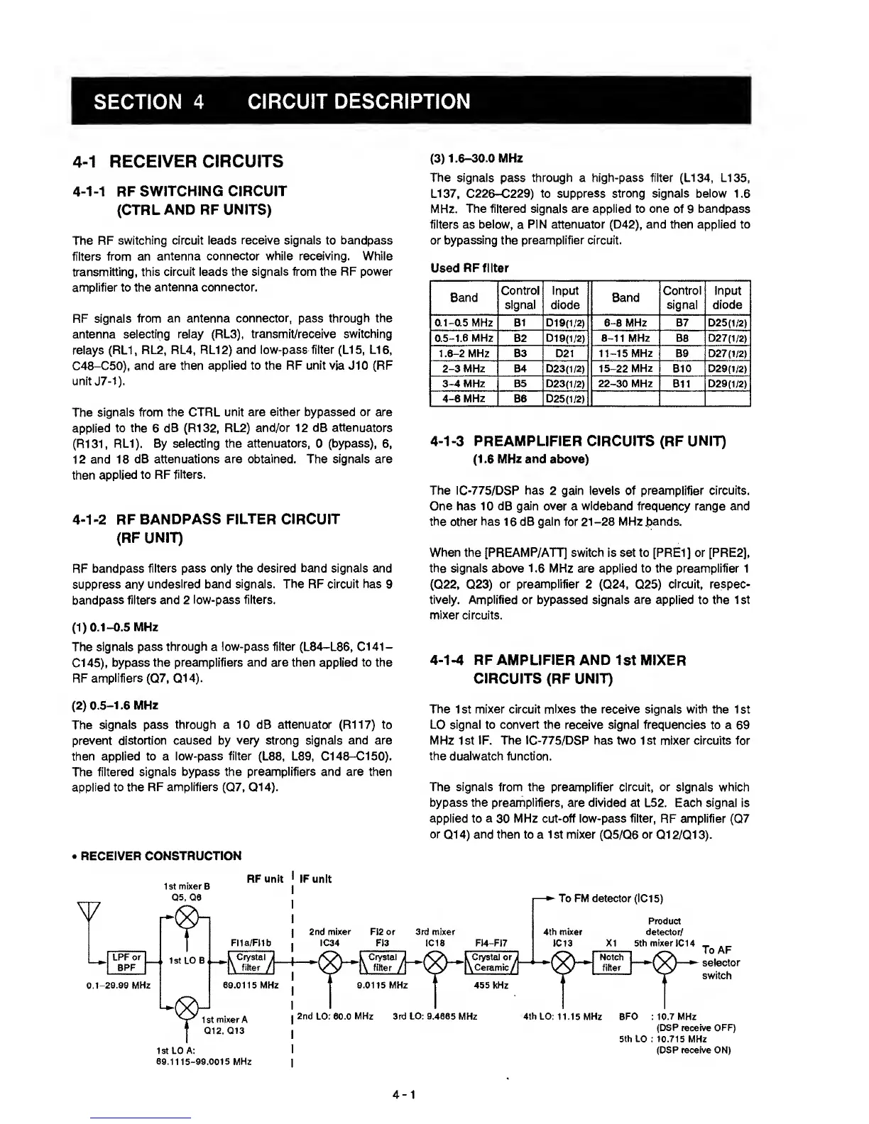
•
RECEIVER CONSTRUCTION
The 1st mixer
circuit mixes
the
receive
signals with the 1st
LO
signal to convert the receive signal
frequencies to a
69
MHz 1st IF. The IC-775/DSP has two 1st mixer circuits for
the dualwatch function.
The signals from the preamplifier circuit, or signals
which
bypass the preamplifiers,
are
divided
at L52. Each
signal
is
applied
to
a
30
MHz cut-off low-pass filter,
RF
amplifier
(Q7
or
Q1
4)
and then to a 1 st mixer
(Q5/Q6
or Q1 2/Ql
3).
RF unit
FI1a/FMb
, Crystal i
\
fiitef
/
89.0115 MHz
1
st mixer
A
Q12,
Q13
IstLO A:
69.1115-99.0015
MHz
IF unit
2nd
mixer
FI2
or 3rd
mixer
IC34 FI3 IC1S FM-FI7
9.0115 MHz
L Ceramic
it
To
FM detector (IC1
5)
4th mixer
IC13
Product
detector/
XI 5th
mixer
IC14
455
kHz
ToAF
selector
switch
2nd LO: 60.0
MHz
3rd
LO: 9.4685
MHz 4th LO:
11.15
MHz
BFO : 10.7 MHz
(DSP
receive
OFF)
5th
LO
:
10.715
MHz
(DSP receive ON)
4-1

 Loading...


