5-3
RECEIVER
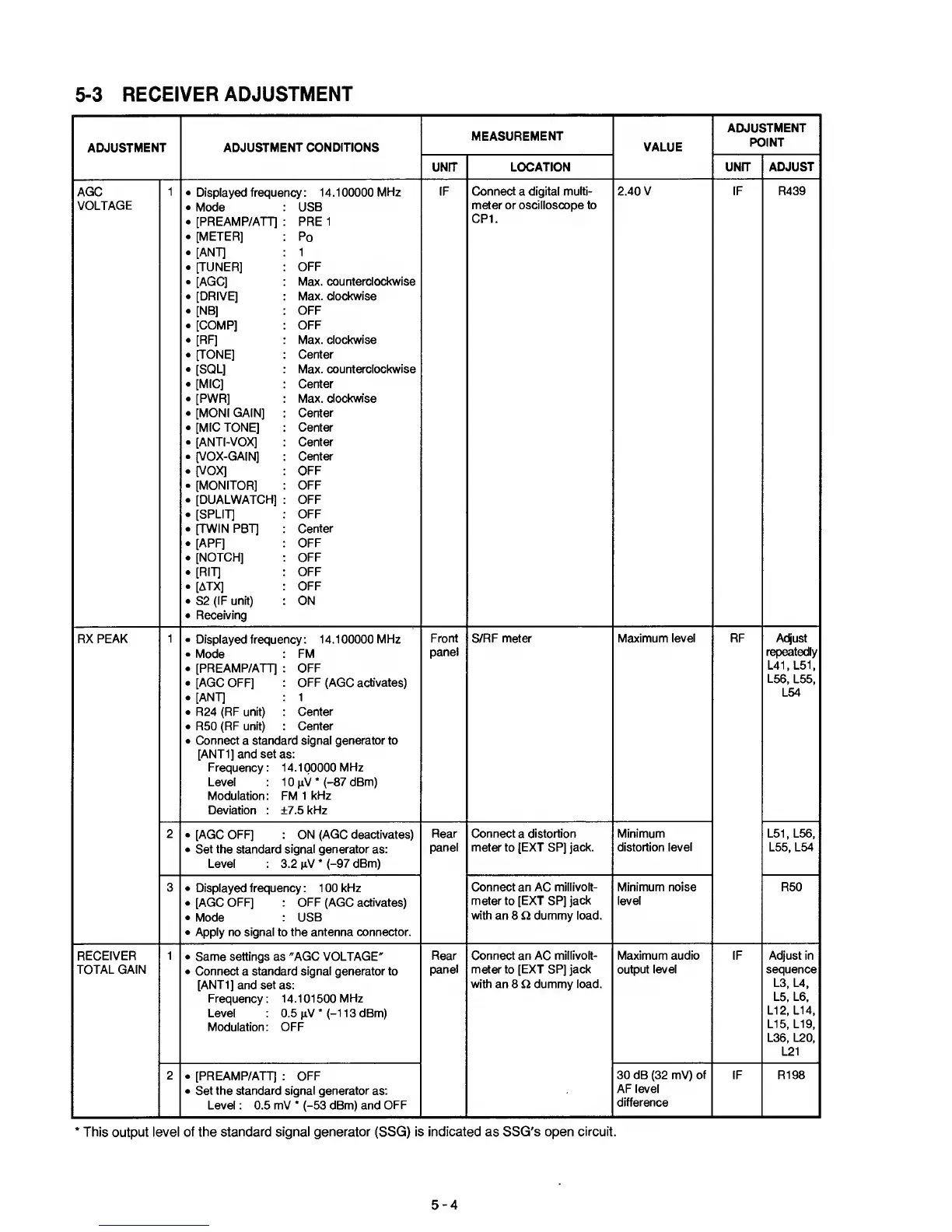
ADJUSTMENT
ADJUSTMENT
ADJUSTMENT CONDITIONS
MEASUREMENT
VALUE
ADJUSTMENT
POINT
UNIT
LOCATION UNIT
ADJUST
AGC
VOLTAGE
1 •
Displayed freque
•
Mode
.
[PREAMP/ATT]
.
[METER]
.
[ANT]
.
[TUNER]
• [AGC]
.
[DRIVE]
•
[NB]
.
[COMP]
•
[RF]
.
[TONE]
•
[SQL]
.
[MIC]
.
[PWR]
.
[MONI GAIN]
•
[MIC TONE]
•
[ANTI-VOX]
•
[VOX-GAIN]
•
[VOX]
• [MONITOR]
.
[DUALWATCH]
•
[SPLIT]
•
[TWIN PBT]
•
[APF]
•
[NOTCH]
•
[RIT]
•
[ATX]
.
S2
(IF unit)
•
Receiving
ncy: 14.100000
MHz
USB
PRE 1
Po
1
OFF
Max.
counterclockwise
Max. clockwise
OFF
OFF
Max.
clockwise
Center
Max.
counterclockwise
Center
Max. clockwise
Center
Center
Center
Center
OFF
OFF
OFF
OFF
Center
OFF
OFF
OFF
OFF
ON
IF Connect a digital
multi-
meter or oscilloscope to
CPI.
2.40 V IF R439
RX PEAK
1 •
Displayed freque
•
Mode
•
[PREAMP/ATT]
.
[AGC
OFF]
.
[ANT]
•
R24 (RF unit)
•
R50 (RF
unit)
•
Connect
a
standt
[ANTI] and set a
Frequency
:
Level
Modulation:
Deviation :
ncy: 14.100000 MHz
FM
OFF
OFF (AGC activates)
1
Center
Center
ird signal generator to
s:
4.100000 MHz
0
pV
*
(-87 dBm)
-M
1 kHz
b7.5 kHz
Front
panel
S/RF meter Maximum
level
RF Adjust
repeatedly
L41,L51,
L56,
L55,
L54
2
•
[AGC OFF] ON (AGC deactivates)
•
Set the standard signal generator
as:
Level :
3.2
pV
*
(-97 dBm)
Rear
panel
Connect
a
distortion
meter to [EXT SP] jack.
Minimum
distortion
level
L51, L56,
L55, L54
3 •
Displayed frequency : 1 00 kHz
.
[AGC
OFF] : OFF (AGC activates)
•
Mode
: USB
•
Apply no signal to the antenna connector.
Connect an AC millivolt-
meter to [EXT SP] jack
with an 8 Q dummy load.
Minimum noise
level
R50
RECEIVER
TOTAL GAIN
1
•
Same settings as "AGC VOLTAGE"
•
Connect
a
standard signal generator to
[ANT1]
and
set
as:
Frequency: 14.101500 MHz
Level :
0.5
pV
*
(-11
3 dBm)
Modulation: OFF
Rear
panel
Connect an AC millivolt-
meter to [EXT SP] jack
with an 8 O dummy load.
Maximum audio
output level
IF Adjust in
sequence
L3, L4,
L5, L6,
L12, L14,
LI
5,
LI
9,
L36, L20,
L21
2
.
[PREAMP/ATT] : OFF
•
Set the standard signal generator
as:
Level : 0.5 mV
*
(-53
dBm) and
OFF
30 dB
(32
mV) of
AF level
difference
IF R198
*
This output level of the
standard signal generator (SSG) is indicated as SSG's open
circuit.
5-4

 Loading...


