4-3-3
2ND
LO
AND REFERENCE
OSCILLATOR
CIRCUITS
The
reference
oscillator (XI,
Q1)
generates a
30.0 MHz
frequency
used
for the
6
DDS
ICs as a system
clock and for
the LO
output. The
oscillated
signal is doubled by 2 at Q2
and
the
60
MHz
frequency is picked up at the
bandpass
filter (L6, L7).
The
60
MHz
signal is applied to the
IF unit as
a 2nd LO
signal.
4-3-4
3RD/4TH LO
AND
RECEIVE/TRANSMIT/
MONITOR
BFO
CIRCUITS
(1)
3rd
LO
circuit
The DDS 1C
(DDS-A
board IC1)
generates a 10-bit
digital
signal
using the 30
MHz system
clock. The digital
signal is
converted
to an
analog wave
signal at the D/A
converter
(R13-R32).
The analog
wave is passed
through the band-
pass filter,
buffer-amplifier
(Q43),
low-pass filter and
is then
applied to the IF
unit as the 3rd
LO
signal.
(2)
4th LO
circuit
The DDS 1C
(DDS-B
board IC1)
generates a 10-bit
digital
signal. The
signal is
converted to
an analog wave
signal at
the D/A
converter.
The analog
wave is passed
through the
bandpass filter,
buffer-amplifier
(Q44),
low-pass filter
and is
then
applied to
the IF unit as the
4th
LO
signal.
(3)
Receive BFO/Sth
LO and
transmit BFO circuits
The DDS 1C
(DDS-C
board IC1)
generates
a 10-bit
digital
signal. The
signal is
converted to an
analog wave signal at
the D/A
converter.
The
analog wave is passed through the
low-pass
filter,
buffer-amplifier
(Q46).
While transmitting in
RTTY
mode, the
RTTY
keying signal is
applied
to
IC1 pin 2
to
shift the
generated
frequency and to
obtain 2 frequencies
for FSK
operation.
(4)
Monitor BFO, side tone and
subaudible tone
circuits
The DDS
1C
(DDS-D
board IC1)
generates a 10-bit
digital
signal. The
signal is converted to
an analog
wave
signal at
the D/A
converter. The analog
wave is passed
through the
low-pass
filter, buffer-amplifier
(Q49).
While transmitting in SSB/RTTY/CW
modes with the
moni-
tor
function, the 9.01
15
MHz BFO
signal passes
through the
high-pass
filter and is then
applied to the IF unit
via the
“MBFO”
signal line.
While
transmitting in CW mode
without the monitor
function,
the sidetone
signal
(300-900
Hz) passes
through the low-
pass
filter
and
is then applied to
the IF unit via the “STON”
signal tine.
While
transmitting in FM mode
with the subaudible tone
function, the subaudible tone
signal (67.0-254.1 Hz)
passes
through the low-pass
filter and is then
applied
to
the IF unit
via the
“STON” signal line.
4-3-5
MARKER CIRCUITS
(MARKER
BOARD)
The
30
MHz
reference signal is
divided by
3
at IC1 and
then
divided by 100
at IC2 to
obtain
a
100 kHz signal and its
harmonic
components
signals. The resulting marker sig-
nals are applied
to the splitter (RF
unit
L52)
which is before
the 1st
mixer
circuits. 02
and
03
supply
power to the
buffer
amplifier
(01)
and switch the marker
signal
output.
4-4
ANTENNA TUNER
CIRCUITS
4-4-1
MATCHING CIRCUIT
(RELAY, CTRL AND
TUNER UNITS)
While
receiving, the
10.7 MHz BFO or
10.715 MHz 5th LO
signal
passes through
the bandpass
filter and is then
applied to the
IF unit
via the “RBFO”
signal line.
While
transmitting, the 455 kHz
BFO or 440 kHz LO
signal
passes through
the low-pass
filter and is then
applied
to
the
IF unit
via the “TBFO”
signal line.
Mode
RX 5th LO
frequency
[MHz]
TX LO/BFO
frequency
[kHz]
USB
10.712125
437.875
LSB
10.709125
440.875
CW
10.709725
(
- CW pitch
frequency)
455.9
(non-DSP)
CW-R
10.709725
(
+ CW
pitch frequency)
455.9
(non-DSP)
RTTY
10.70750 (2125
Hz tone)
10.70801 (1615
Hz tone)
456.0
(non-DSP, MARK)
RTTY
DATA
10.707500 (2125
Hz tone)
1
0.708555 (1
070 Hz tone)
440.875
AM/FM
No
output No
output
RTTY:
Normal polarity
DSP: ON INOTCH]:
Center
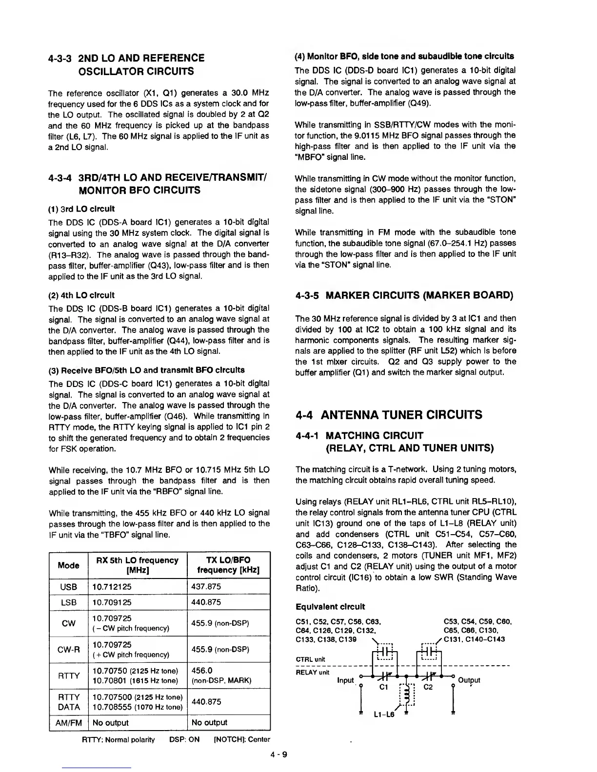
The
matching circuit is a
T-network. Using 2 tuning motors,
the
matching circuit
obtains rapid overall tuning speed.
Using relays (RELAY unit
RL1-RL6, CTRL unit RL5-RL10),
the relay
control signals from the antenna tuner
CPU (CTRL
unit
1C13)
ground
one of the taps of L1-L8
(RELAY unit)
and add condensers (CTRL
unit
C51-C54, C57-C60,
C63-C66,
C128-C133, C138-C143).
After selecting the
coils and condensers, 2
motors (TUNER unit MF1, MF2)
adjust
Cl and
C2
(RELAY unit)
using the output of a motor
control circuit (IC16) to obtain a low SWR
(Standing Wave
Ratio).
Equivalent circuit
C51, C52, C57, C58, C63,
C53, C54, C59, C60,
C64, Cl
28,
Cl
29,
Cl
32,
C65, C66, C130,
C133, C138, C139
CTRL
unit
\
rHI4i
f4H
hh
C131,
C140-C143
RELAY unit
Input
Output
?
Cl C2
?
'
i /I"
*
L1-L8
*
4-9

 Loading...


