EasyManuals Logo
Home>Icom>Transceiver>IC-A200

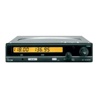
Icom IC-A200 User Manual

Icom IC-A200
16 pages
To Next Page IconTo Next Page
To Previous Page IconTo Previous Page
Page #5 background imageLoading...
Page #5 background image
@
Function
display
wi
id
-
(LS
CH
Es
®
9
@USE
WINDOW
Indicates
the
operating
frequency
that
is
used
for
trans-
mitting
and
receiving.
@
TRANSMIT
INDICATOR
Appears
while
transmitting.
(p.
6)
@OSTBY
WINDOW
Indicates
the
standing-by
frequency
which
is
used
as
the
next
operating
frequency.
—When
a
memory
channel
is
recalled,
indicates
the
memory
channel
frequency
content.
©
MEMORY
CHANNEL
INDICATOR
Indicates
a
selected
memory
channel
number.
(pgs.
7~10)
@
PROGRAMMING
INDICATOR
Indicates
that
a
memory
channel
can
be
programmed.
(pgs.
7~8)
PANEL
DESCRIPTION
1
i
Remote
switches
and
jacks
The
following
switches
and
jacks
can
be
installed
on
your
aircraft.
Ask
your
Icom
Avionics
Dealer
for
wiring.
Headphone
Jack
Connects
a
500
Q
headset.
Microphone
audio
jack
Connects
a
low-impedance
carbon
or
dynamic
microphone.
A
preamplifier
is
required
for
a
dynamic
microphone.
Yoke-mounted
communicatlon/intercom
switch
—Set
to
the
“communication”
position
for
the
air
band.
(p.
6)
—Set
to
the
“intercom”
position
to
talk
with
a
crew
member.
This
allows
communication
between
the
pilot
and
co-pilot.
(p.
6)
Yoke-mounted
channel
switch
Remotely
selects
a
memory
channel.
(p.
9)
¢
Cannot
be
used
for
memory
channel
programming.
Yoke-mounted
frequency
exchange
switch
Remotely
exchanges
the
USE
window
frequency
for
the
STBY
window
frequency
and
vice
versa.

Other manuals for Icom IC-A200

Questions and Answers:

Question and Answer IconNeed help?

Do you have a question about the Icom IC-A200 and is the answer not in the manual?

Icom IC-A200 Specifications

General IconGeneral
BrandIcom
ModelIC-A200
CategoryTransceiver
LanguageEnglish

Related product manuals