4-10g
ADJUSTMENT ADJUSTMENT SETUP OPER ATION
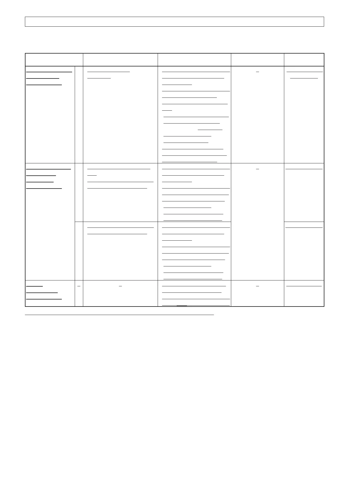
ADJUSTMENT
ITEM/POINT
VALUE
HEADSET AUDIO
DISTORTION
~Verification~
1
CH No.: [AM Mid]
Receiving
Connect the distortion meter
with the 500 load to the
headset line.
Connect the standard signal
generator (SSG) to the
antenna connector, and set
it to:
Frequency: 127.500 MHz
(53 dBm)
Modulation: 1 kHz
Deviation: 85%
Set the audio output level
so that the distortion meter
shows 5.48 V (60 mW).
Less than 10%
of distortion
For only IC-A220:
INTERCOM
FUNCTION
~Verification~
1
Turn the intercom function
ON.
Set the "INCOM LV1" in the
configulation menu to 60.
Connect the distortion meter
with the 500 load to the
headset line.
Connect the audio generator
with the AC millivoltmeter to
the MIC1 line, and set it to:
Frequency: 1 kHz
Level: 20 mV rms
Waveform: Sine wave
2.16 ~3. 24 Vrms
2
Set the "INCOM LV2" in the
configulation menu to 60.
Connect the distortion meter
with the 500 load to the
headset line.
Connect the audio generator
with the AC millivoltmeter to
the MIC2 line, and set it to:
Frequency: 1 kHz
Level: 20 mV rms
Waveform: Sine wave
2.16 ~3. 24 Vrms
27.5 V
OPER ATION
~Verification~
1 Connect the 27.5 V power
source to the transceiver.
Connect the digital voltmeter
to the CP2 on the MAIN unit.
13.5 V (±0.5 V)
*The output level of the standard signal generator (SSG) is indicated at the load end (PD).
(Replacement page)
July 2019
The underlined parts have been updated from the previous version of the addendum, or the original page.
4-4 RECEIVER ADJUSTMENTS (CONTINUED)

 Loading...


