4-3g
(Replacement page)
July 2019
4-2 FREQUENCY ADJUSTMENT
ADJUSTMENT ADJUSTMENT SETUP OPER ATION
ADJUSTMENT
ITEM/POINT
VALUE
VDD VOLTAGE
~Adjustment~
(RX)
1 CH No.: [AM Mid]
Receiving
Connect the 13.8 V power
source to the transceiver.
Connect the digital voltmeter
to the CP2 on the MAIN unit.
[F13]
(Adjustment screen)
13.5 V (±0.1 V)
LOCK VOLTAGE
~Adjustment~
(RX)
1 CH No.: [AM High]
Receiving
Connect the digital voltmeter
to the CP1 on the MAIN unit.
C136
(MAIN unit)
3.5 V (±0.1 V)
(TX) 2 CH No.: [AM High]
Transmitting
C127
(MAIN unit)
~Verification~
(RX)
3 CH No.: [AM Low]
Receiving
More than
0.5 V
(TX) 4 CH No.: [AM Low]
Transmitting
REFERENCE
FREQUENCY
~Adjustment~
1 CH No.: [AM High]
Transmitting
Connect the RF power
to the antenna connector.
Loose couple the frequency
counter to the antenna
connector.
[F1]
(Adjustment screen)
136.975 MHz
(±100 Hz)
2
†
Receiving [F25]
(Adjustment screen)
Enter the
same
adjustment
value of the
[F1].
†
For only IC-A220.
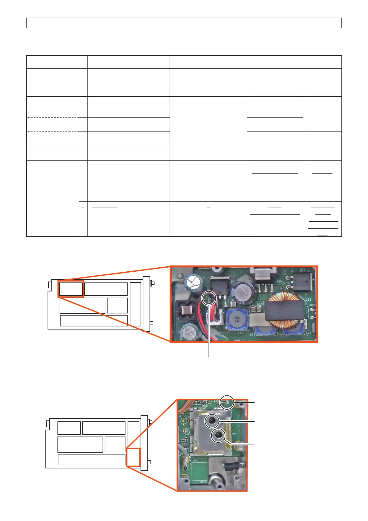
• VDD voltage (RX) check point
(TOP VIEW)
CP2
VDD voltage check point
• Lock voltage (RX and TX) adjustments
(TOP VIEW)
C127
PLL Lock voltage (TX)
adjustment
CP1
PLL Lock voltage
check point
C136
PLL Lock voltage (RX)
adjustment
The underlined parts have been updated from the previous version of the addendum, or the original page.

 Loading...


