4-1g
SECTION 4 ADJUSTMENT PROCEDURES
(Replacement page)
July 2019
4-1 PREPARATION
■ REQUIRED EQUIPMENT
EQUIPMENT GRADE AND RANGE EQUIPMENT GRADE AND RANGE
Adjustment
software
CS-A210 ADJ (for IC-A210/IC-A210E),
or CS-A220ADJ (for IC-A220)
(Revision 1.0 or later)
Standard signal
generator (SSG)
Frequency range: 0.1~300 MHz
(–127 to –17 dBm)
AC millivoltmeter Measuring range: 10 mV to 10 V
Power supply
Output voltage: 13.8 V/27.5 V DC
Current capacity: More than 10 A
Distortion meter
Measuring accuracy
: 3% or less at 1 kHz
Input level: 50 mV to 10 V
RF power meter
Measuring range: 0.1~50 W
Frequency range: 100~300 MHz
SWR: Less than 1.2 : 1
External
speaker
Power rating: More than 10 W
Headphone
speaker
Input impedance: 500
Power rating: More than 60 mW
Oscilloscope
Frequency range: DC~20 MHz
Measuring range: 0.01~20 V
JIG cable
Modified molex
®
cable (See the illust
below)
Modulation
analyzer
Frequency range: 30~300 MHz
Measuring range: 0~100%
Frequency counter
Range: 0.1~300 MHz
Accuracy: ±1 ppm or better
Spectrum analyzer Measuring range: Up to 3 GHz Digital voltmeter Measuring range: 0.1~10 V
Audio generator
(AG)
Frequency range: 300~3000 Hz
Output level: 1~500 mV
Attenuator
Attenuation: 30 dB
Power rating: More than 50 W
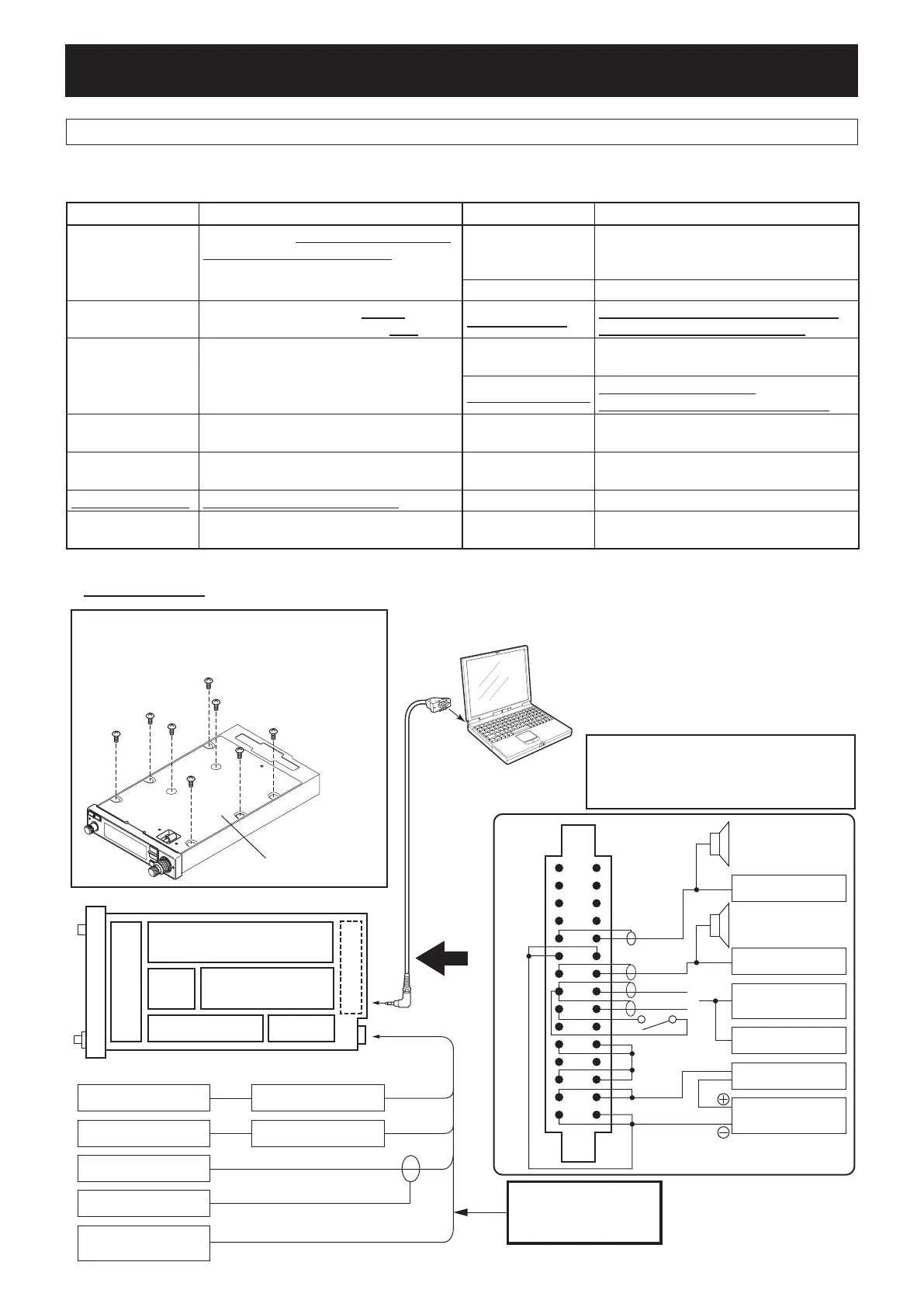
■ CONNECTIONS
to the antennna connector
To K-CONNECT UNIT
To [DATA] jack
Power supply
(13.8 V/27.5 V: 10 A)
Audio generator
(AG)
Distortion meter
AC milivoltmeter
Ammeter (10 A)
External speaker
(4 Ω)
Distortion meter
Headphone speaker
(500 Ω)
PTT
MIC1
MIC2
or
Attenuator
Attenuator
Modulation analyzer
Spectrum analyzer
RF Power meter
Frequency counter
Standard signal
generator (SSG)
OPC-1529R
PC
SYSTEM REQUIREMENTS
For CS-A210 ADJ:
• Microsoft
®
Windows
®
Me/2000/XP and Windows Vista™
• RS-232C serial port (D-sub 9 pin)
For CS-A220ADJ:
• Microsoft
®
Windows
®
Vista™, Windows
®
7/8/8.1
• RS-232C serial port (D-sub 9 pin)
REMOVE THE TOP COVER before adjustment.
Before starting adjustment, remove the top cover
from the chassis to expose the MAIN UNIT.
(DO NOT remove the bottom cover)
USE K-CONNECT UNIT for adjustment.
If MB-113 is atattached to the transceiver,
attach the original rear unit ‘K-CONNECT
UNIT.’ MB-113 has no [DATA] jack.
CAUTION:
DO NOT transmit while
the SSG is connected.
1
2
3
4
5
6
7
8
9
10
11
12
13
14
15
A
B
C
D
E
F
H
J
K
L
M
N
P
R
S
(TOP VIEW)
JIG cable
Top cover
The underlined parts have been updated from the previous version of the addendum, or the original page.