4-5g
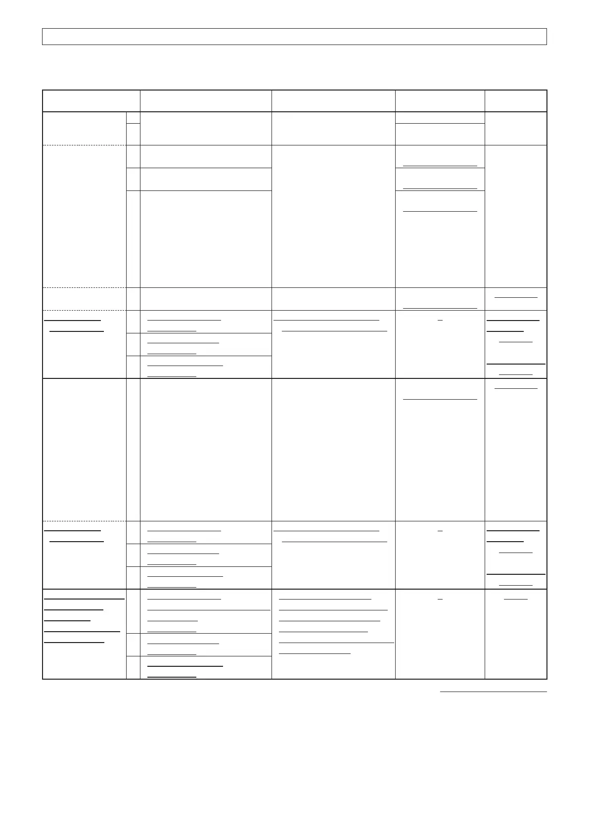
ADJUSTMENT ADJUSTMENT SETUP OPER ATION
ADJUSTMENT
ITEM/POINT
VALUE
MIC1 DEVIATION
AND MIC GAIN
~Preparation~
1 Set the preset value on the
adjustment screen.
[F11] 75
2 [F12]
~ Modulation
adjustment~
3 CH No.: [AM Low]
Transmitting
Connect the modulation
analyzer to the antenna
connector through the
attenuator, and set it to:
HPF: OFF
LPF: OFF
De-emphasis: OFF
Detector: (P-P)/2
Connect the audio generator
to the MIC1 line, and set it to:
Frequency: 1 kHz
Level: 300 mV rms
Waveform: Sine wave
[F8]
(Adjustment screen)
88% (±2%)
4 CH No.: [AM Mid]
Transmitting
[F9]
(Adjustment screen)
5 CH No.: [AM High]
Transmitting
[F10]
(Adjustment screen)
~ MIC gain
adjustment~
6 CH No.: [AM Mid]
Transmitting
Set the audio generator to:
Level: 80 mV rms
[F11]
(Adjustment screen)
75% (±5%)
~ Modulation
verification~
7
CH No.: [AM Low]
Transmitting
Set the audio generator to:
Level: 100 mV rms
For IC-A210/
IC-A220:
70~98%
For IC-A210E:
85~95%
8
CH No.: [AM Mid]
Transmitting
9
CH No.: [AM High]
Transmitting
MIC2 DEVIATION
AND MIC GAIN
~Adjustment~
1 CH No.: [AM Mid]
Transmitting
Connect the modulation
analyzer to the antenna
connector through the
attenuator, and set it to:
HPF: OFF
LPF: OFF
De-emphasis: OFF
Detector: (P-P)/2
Connect the audio generator
to the MIC2 line, and set it to:
Frequency: 1 kHz
Level: 80 mV rms
Waveform: Sine wave
[F12]
(Adjustment screen)
75% (±5%)
~ Modulation
verification~
2
CH No.: [AM Low]
Transmitting
Set the audio generator to:
Level: 100 mV rms
For IC-A210/
IC-A220:
70~98%
For IC-A210E:
85~95%
3
CH No.: [AM Mid]
Transmitting
4
CH No.: [AM High]
Transmitting
For only IC-A210E:
TX FLOWING
CURRENT
(UNMODULATED)
~Verification~
1
CH No.: [AM Low]
No audio signals are applied to
the MIC line.
Transmitting
Connect the RF power
meter or 50 dummy load
to the antenna connector.
Connect the ammeter
between the transceiver and
the power source.
1~4 A
2
CH No.: [AM Mid]
Transmitting
3
CH No.: [AM High]
Transmitting
(Replacement page)
July 2019
4-3 TRANSMIT ADJUSTMENTS (CONTINUED)
The underlined parts have been updated from the previous version of the addendum, or the original page.
Continued on the next page…

 Loading...


