EasyManua.ls Logo

Icom IC-A6 User Manual

Icom IC-A6
44 pages
To Next Page IconTo Next Page
To Previous Page IconTo Previous Page
Page #18 background imageLoading...
Page #18 background image
14
4
MEMORY OPERATION
Memory names
Programming memory names ï
The memory channel can display a 6-character name in-
stead of the programmed frequency.
q In the frequency mode, rotate [DIAL] to select the desired
frequency in the frequency mode.
w Push
,
then push [MR•MW] to program the contents
into the selected memory channel.
e Rotate [DIAL] to select the desired memory channel to be
programmed.
Push , then push [0•BANK], and rotate [DIAL] to select the
BANK number, if desired. Push [CLR•DEL] to exit the BANK se-
lection mode.
r Push [MR•MW] to enter the memory name programming
mode.
• “-- -- -- -- -- -- ” appears on the display.
t Push the appropriate digit key several times to select the
desired character, as listed to the right.
To erase a character, overwrite with a space (displayed as _).
To move the cursor forwards or backwards, use [DIAL].
y Push [ENT•WX] to program the name.
The memory name stops ashing.
When no name is programmed, the display shows the operat-
ing frequency.
To clear the entered memory names, push [CLRDEL] before
pushing [ENT•WX].
NOTE: When programming the memory name to the pro-
grammed memory channel do the following.
q Follow the same steps as in “Transferring memory con-
tents” (see p. 12).
w Follow steps wy in “Programming memory names”
(see left column).
Clearing the memory contents
Unwanted memory channels can be cleared.
q Select the memory channel to be cleared.
w Push
,
then hold down [CLR•DEL] for 1 second.
“-- -- -- -- -- --” appears momentarily, then the next selectable
channel appears.
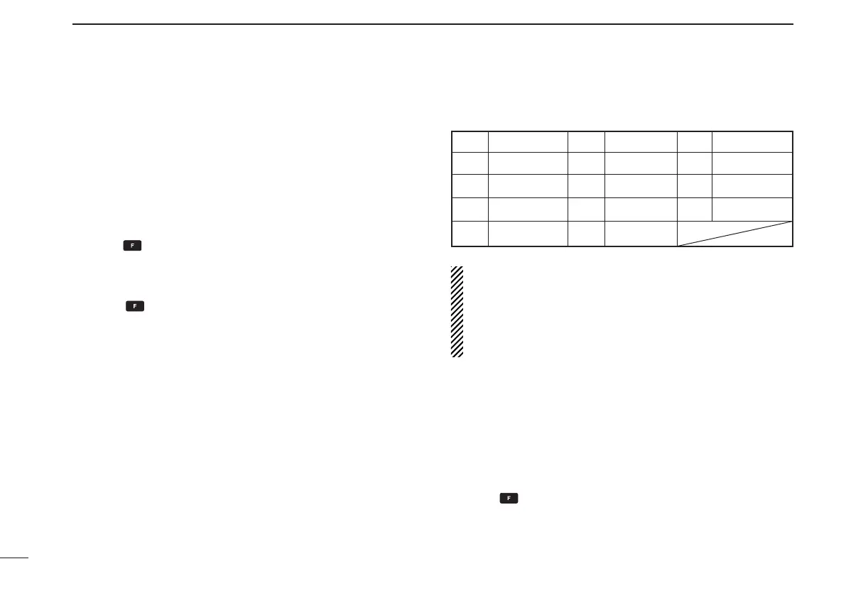
Key Character Key Character Key Character
1 1, Q, Z 2 2, A, B, C 3 3, D, E, F
4 4, G, H, I 5 5, J, K, L 6 6, M, N, O
7 7, P, R, S 8 8, T, U, V 9 9, W, X, Y
ENT Program 0 0, space, -

Table of Contents

Other manuals for Icom IC-A6

Questions and Answers:

Icom IC-A6 Specifications

General IconGeneral
Frequency Range118.000–136.975 MHz
Channel Spacing25 kHz
Antenna Impedance50Ω
Power Supply Requirement7.2 V DC
WaterproofNo
Channels200 channels
Current Drain1.5 A (at max output)
RF Output Power5 W (PEP)
ModulationAM
Battery Life15 hours
Weight430g
Dimensions54 x 129.3 x 35.5 mm

Summary

Foreword and Important Information

Foreword

Introduction to the Icom transceiver and its quality.

Important Usage Instructions

Key instructions to read before operating the transceiver.

Explicit Definitions

Definitions of warning symbols and terms used in the manual.

Supplied Accessories

List of items included with the transceiver and their quantities.

Precautionary Warnings

Safety Precautions

Critical safety warnings for operating the transceiver and handling batteries.

Accessory Attachment Procedures

Antenna Attachment

Instructions for connecting the supplied antenna to the transceiver.

Belt Clip Attachment

Guidance on attaching the belt clip to the transceiver.

Battery Pack Removal

Procedure for removing the battery pack from the transceiver.

Transceiver Panel Description

Transceiver Front Panel Layout

Diagram and labels of the transceiver's front panel controls.

Panel Controls: Switches and Dials

Description of backlight, PTT, volume, dial, antenna, recall, squelch, power, jacks, function keys.

Panel Controls: Keys and Jacks

Description of clear, ANL, emergency, power jack, memory, enter keys.

Digit Keys and Secondary Functions

Details on digit keys and their secondary functions.

Display Indicators: Status Icons

Explanation of function, TX/RX, duplex, low battery, lock indicators.

Display Indicators: Navigation and Data

Explanation of frequency, tag, memory, bank, overflow, ANL, course indicators.

Basic Operation Guide

Setting Operating Frequency

How to set operating frequencies using keypad or dial.

Selecting Weather Channels (USA Only)

How to select weather channels for flight planning.

Receiving Signals

Steps to receive signals and adjust audio.

ANL Noise Limiter Function

Reduces noise during reception.

Setting Channel Spacing

How to set channel spacing (8.33/25 kHz).

Adjusting Squelch Level

Adjusting the squelch to mute noise.

Transmitting Procedures

Procedures for transmitting signals.

Low Battery Indicator

Indicates when the battery needs recharging.

Recall Function

Stores and recalls the last 10 frequencies used.

Deleting Recall Channels

Procedure to delete recall channels.

Replacing Recall Channels

Procedure to replace recall channels.

Setting Weather Alert Function

Enables alert tone for weather announcements.

Accessing 121.5 MHz Emergency Frequency

Quickly selects the 121.5 MHz emergency frequency.

Using the Lock Function

Prevents accidental key presses.

Side Tone Monitoring Function

Monitors transmitted voice through headset.

Adjusting Beep Tone

Adjusts the beep tone level for key presses.

Memory Operation Guide

Selecting Memory Channels

How to select memory channels.

Transferring Memory Data

Moves memory channel data to frequency mode.

Programming Memory Channels

Steps to store frequencies into memory channels.

Example: Programming Weather Channel into Memory

Example of programming a weather channel into memory.

Assigning Memory Names

How to assign 6-character names to memory channels.

Procedure for Programming Memory Names

Detailed steps for assigning names.

Clearing Memory Channels

How to delete unwanted memory channels.

Example: Programming Frequency and Name

Example of programming frequency and comment for memory.

Scan Operation Guide

Overview of Scan Types

Overview of available scan types (COM, Memory, Weather).

Scanning the COM Band

Procedure to scan frequencies in the COM band.

Performing Memory Scan

Procedure to scan programmed memory channels.

Scanning Weather Channels (USA Only)

Procedure to scan weather channels.

Setting TAG Channels for Scan

How to set channels to be skipped or included in scans.

VOR Navigation (IC-A24 ONLY)

Understanding VOR Indicators

Explains the indicators used in VOR navigation display.

Using VOR Navigation Functions

How to use VOR navigation features.

Selecting TO/FROM Flag

How to select the TO or FROM flag indicator.

Switching VOR Stations in CDI Mode

How to switch to another VOR station while in CDI mode.

Navigating to a VOR Station

Guide to navigating to a VOR station.

Note on VOR Localizer Indicator

Information about the 'loc' indicator for localizer signals.

Example: Entering Desired Course Bearing

Example of entering a desired course bearing for navigation.

Setting a Desired Course

How to set a desired course for VOR navigation.

Crosschecking Position with Two VOR Stations

How to determine position using two VOR stations.

Using the ABSS Function

Explanation of the Auto Bearing Set System.

Example: VOR Navigation Process Illustration

Illustrates the process of navigating to a VOR station.

Cloning Procedures

Cloning: Transceiver to Transceiver

Procedure for transferring data between transceivers.

Cloning: Using a PC

Procedure for transferring data between PC and transceiver.

Handling Cloning Errors

What to do if a cloning error occurs.

Example: Transceiver Cloning Procedure

Illustrates the process of cloning between transceivers.

Battery Pack Information

Battery Handling Cautions

Critical safety warnings regarding battery handling.

Battery Charging Procedures

Instructions and precautions for charging the battery pack.

Performing Regular Battery Charging

Steps for regular charging of the battery pack.

Using the Optional Battery Case

How to install and use alkaline batteries in the case.

Optional Battery Charger Details

Information on installing and using optional chargers.

Rapid Charging with BC-119N+AD-101

Details on rapid charging using BC-119N.

Rapid Charging with BC-121N+AD-101

Details on rapid charging using BC-121N.

Technical Specifications

General Technical Specifications

Technical specifications like frequency, mode, channels, power.

Transmitter Technical Specifications

Specifications related to the transmitter output.

Receiver Technical Specifications

Specifications related to the receiver sensitivity.

VFO Channel ID List

Lists channel IDs for different frequencies and spacing.

Optional Equipment and Accessories

Optional Battery Cases and Packs

List of available battery cases and packs.

Optional Chargers

List of optional chargers for the transceiver.

Optional Microphones

Optional microphone accessories.

Optional Belt Clips

Optional belt clip accessories.

Optional DC Cables

Optional DC power cables.

Other Optional Accessories

Miscellaneous optional accessories.

Optional Headset Connection

Headset Adapter Connection (OPC-499)

How to connect an optional headset via adapter.

Safety Training Information

RF Exposure and Safety Guidelines

Information on RF exposure limits and safe usage practices.

Electromagnetic Interference and Compatibility

How transmissions can interfere with other devices.

Occupational Use Guidelines

Explains the intended usage environment for the radio.

Class A Unintentional Radiators Compliance

FCC Compliance for Class A Devices

Statement regarding compliance with FCC rules for Class A devices.

Troubleshooting Common Issues

Problem/Solution Guide

Lists common issues and their resolutions.

Replacing CP-20 Fuse

Procedure for replacing the fuse in the CP-20 cable.

Related product manuals