4 - 6
4-3 FREQUENCY SYNTHESIZER
VCOs
This transceiver has 3 VCOs; Left band VCO, Right band RX
VCO and Right band TX/RX VCO.
LEFT BAND VCO (Q111, D145–147)
This VCO oscillates 1st LO signals for Left band RX and TX
signal for VHF band.
<While receiving>
The VCO output signal is amplifi ed by buffer (Q113) and LO
amplifier (IC44), and applied to the LO filters according to
the RX frequency.
• While Receiving 118–174 MHz signals
LO signals 135.575−255.575 MHz are applied to the divider
(IC43) via LO switch (D150) and attenuator (R706, 710,
711), and divided into 271.15−511.15 MHz signals. The
divided LO signals are buffer-amplified by Q116, and applied
to the left band 1st mixer (IC19) via the LPF (L115, 156,
C809, 812, 816) and another LO switch (D156).
• While Receiving 174–260 MHz signals
LO signals 141.15−221.145 MHz are passed through the
LPF (L148, 152, C785, 789, 795, 804) via LO switches (D151,
153), and applied to the left band 1st mixer (IC19).
• While Receiving 375–550 MHz signals
LO signals 135.575−255.575 MHz are doubled to 271.15−
511.15 MHz signals, by being passed through the HPF (L149,
C787, 790, 791), LPF (L151, C794, 796, 799) and HPF
(L153, C800, 807) via LO switches (D152, 154). The doubled
LO signals are applied to the left band 1st mixer (IC19).
<While transmitting>
The VCO output signal is amplifi ed by buffer (Q113) and LO
amplifier (IC44), and applied to the transmit amplifiers via
the LO switches (D155, 157), LPF(L157, C818, 820) and
attenuator (R33, 37, 46).
RIGHT BAND RX VCO (Q72, D89, 90)
This VCO oscillates 1st LO signals for right band RX (118–
174 MHz and 810–1000 MHz).
The VCO output signal is amplified by buffer (Q74) and
applied to the LO amplifier (IC45) via VCO switch (D160),
and applied to the LO fi lters according to the RX frequency.
• While Receiving 118–174 MHz signals
LO signals 164.35−220.35 MHz are passed through the LPF
(L123, 125, C529, 534, 539) via LO switches (D107, 159),
and applied to the right band 1st mixer (IC20).
• While Receiving 810–1000 MHz signals
LO signals 381.825−476.82 MHz are applied to the LO
amplifier (IC62) via LO switch (D101). The amplified LO
signals are doubled to 763.65−953.64 MHz signals by being
passed through the HPF (L130, 133, C554, 558, 560), LPF
(L151, C794, 796, 799) and HPF (L135, C563, 568).
The doubled LO signals are applied to the right band 1st
mixer (IC20).
RIGHT BAND TX/RX VCO (Q73, D87, 91, 92)
This VCO oscillates 1st LO signals for right band RX (375–
550 MHz).
<While receiving>
LO signals 353.65−523.17 MHz are passed through the
RF mute switch (Q79) and LPF (L131, 134, C562) via LO
switches (D104, 108), and applied to the right band 1st
mixer (IC20).
<While transmitting>
The VCO output signal is amplified by buffer (Q76), and
applied to the LO amplifier (IC45) via the VCO switch
(D102). The amplifi ed LO signals are applied to the transmit
amplifi ers via the LO switch (D103), two HPFs (L124, C527,
532; L159, C533, 535) and attenuator (R43, 47, 57).
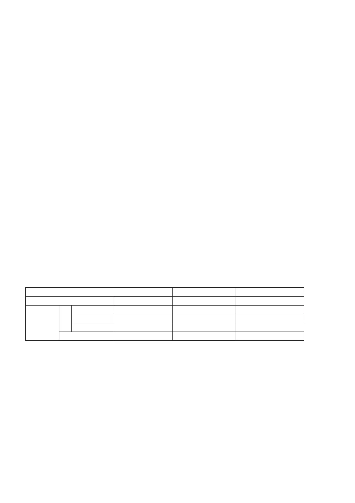
VCO
LEFT BAND VCO RIGHT BAND RX VCO RIGHT BAND TX/RX VCO
Components
(Q111, D145–147) (Q72, D89, 90) (Q73, D87, 91, 92)
Oscillating
Frequency
RX
(118–174 MHz) 135.575−255.575 MHz 164.35−220.35 MHz –
(174–260 MHz) 141.15−221.145 MHz 381.825−476.82 MHz –
(375–550 MHz) 135.575−255.575 MHz – 353.65−523.17 MHz
TX
136–174 MHz – 400–470 MHz
• VCO CONFIGULATION BY FREQUENCY

 Loading...