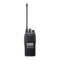
to an RS-232C port
Personal
computer
to [MIC]
to [SP]
JIG cable
DB9 female plug
(incl. level converter circuit)
CONNECTION
to the antenna connector
RF power meter
0.1 10 W/50
Frequency
counter
Attenuator
40 dB or 50 dB
FM
deviation meter
Standard signal generator
0.1 V to 32 mV
( 127 dBm to 17 dBm)
SINAD meter
Speaker (8 )
Audio generator
OPC-478
CAUTION:
DO NOT transmit while
an SSG is connected to
the antenna connector.
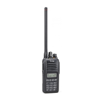
DC POWER
SUPPLY
GND
+
Battery type detectorBattery type detector
DC POWER CABLE CONNECTIONS
NOTE: When you adjust the output power (high
power), the battery type detector must be con-
nected to GND (see illustration at above).
Ohterwise the transceiver does not transmit high
power, the output power will be low.
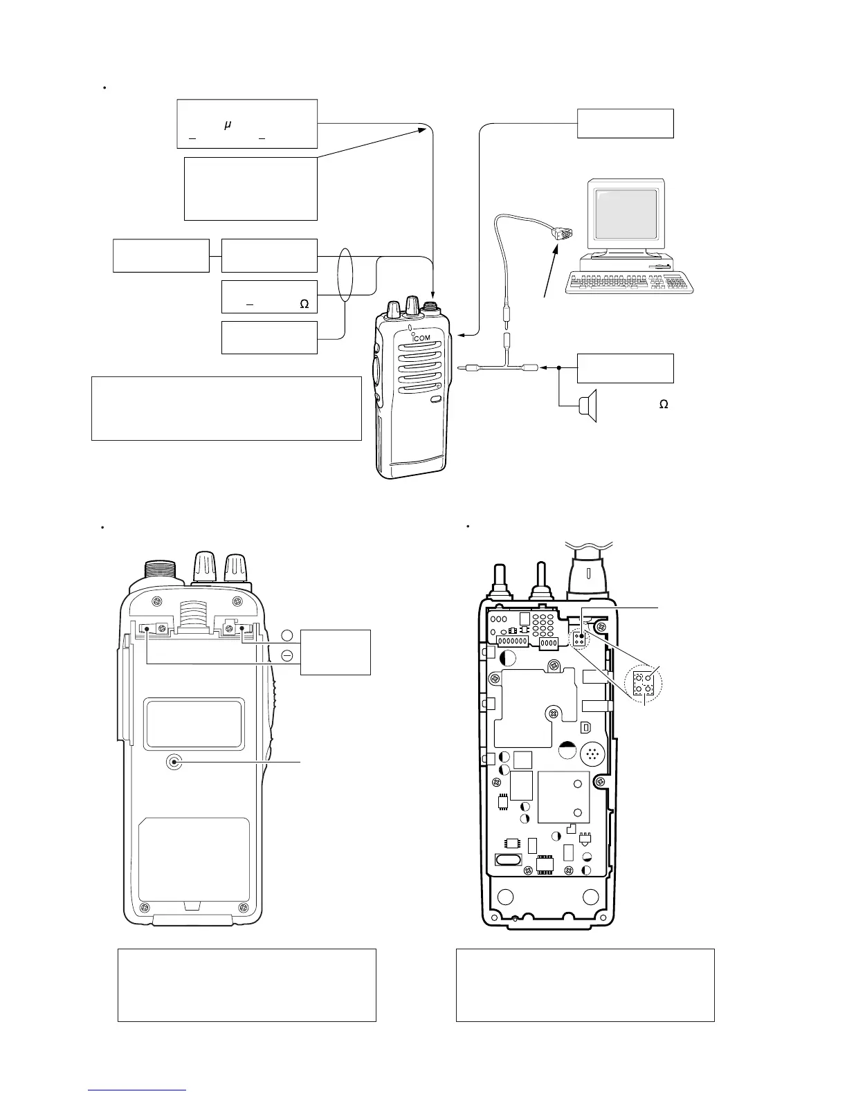
IC-F22SR ANTENNA CONNECT POINT
Signal terminal
GND terminals
J7
NOTE: In case of IC-F22SR, instead of connecting
the Standard Signal Generator, RF power meter,
etc to the antenna connector, connect to the J7 as
shown below.
NOTE: When adjusting SOFTWARE ADJUST-
MENT of IC-F22SR, connect the Standard Signal
generator, RF power meter, etc to the J7 (See
illustration at above).

 Loading...