3 - 1
SECTION 3 DISASSEMBLY INSTRUCTIONS
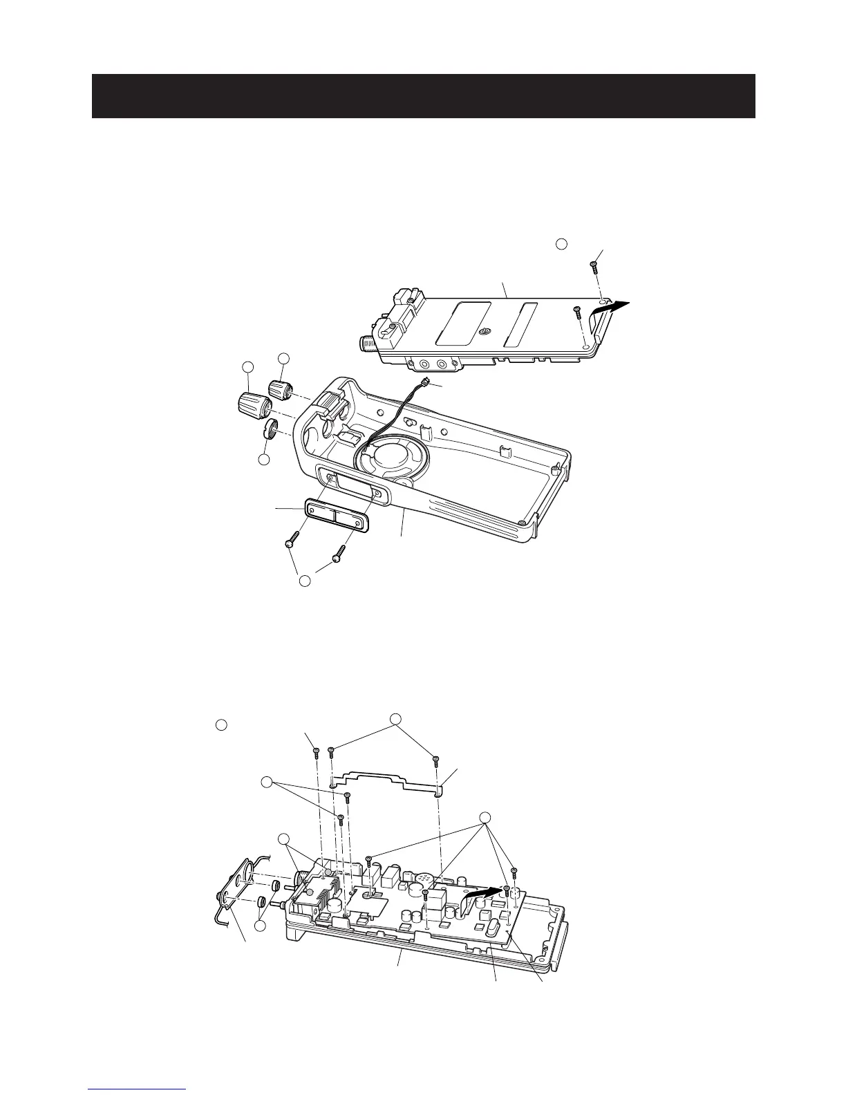
• REMOVING THE CHASSIS
¡ Unscrew 1 nut, A, and remove 2 knobs, B, C.
™ Unscrew 2 screws, D.
£ Unscrew 2 screws, H, to separate the Jack panel and the
Front panel.
¢ Take off the chassis in the direction of the arrow.
∞ Unplug J6 to separate the front panel and the chassis.
• REMOVING THE MAIN UNIT
¡ Remove the searing rubber.
™ Unsolder 2 points, E, and unscrew 2 nuts, F.
£ Unscrew 9 screws, G, (silver, 2mm) to separate the chassis and the MAIN unit.
¢ Take off the MAIN unit in the direction of the arrow.

 Loading...