‘‘
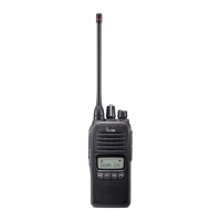
LED indicator
The TX/RX indicator LED indicates several
more information as follows;
(Ref.; R=Red, G=Green, O=Orange)
2
ACCESSORIES
PANEL DESCRIPTION
1
43
‘‘
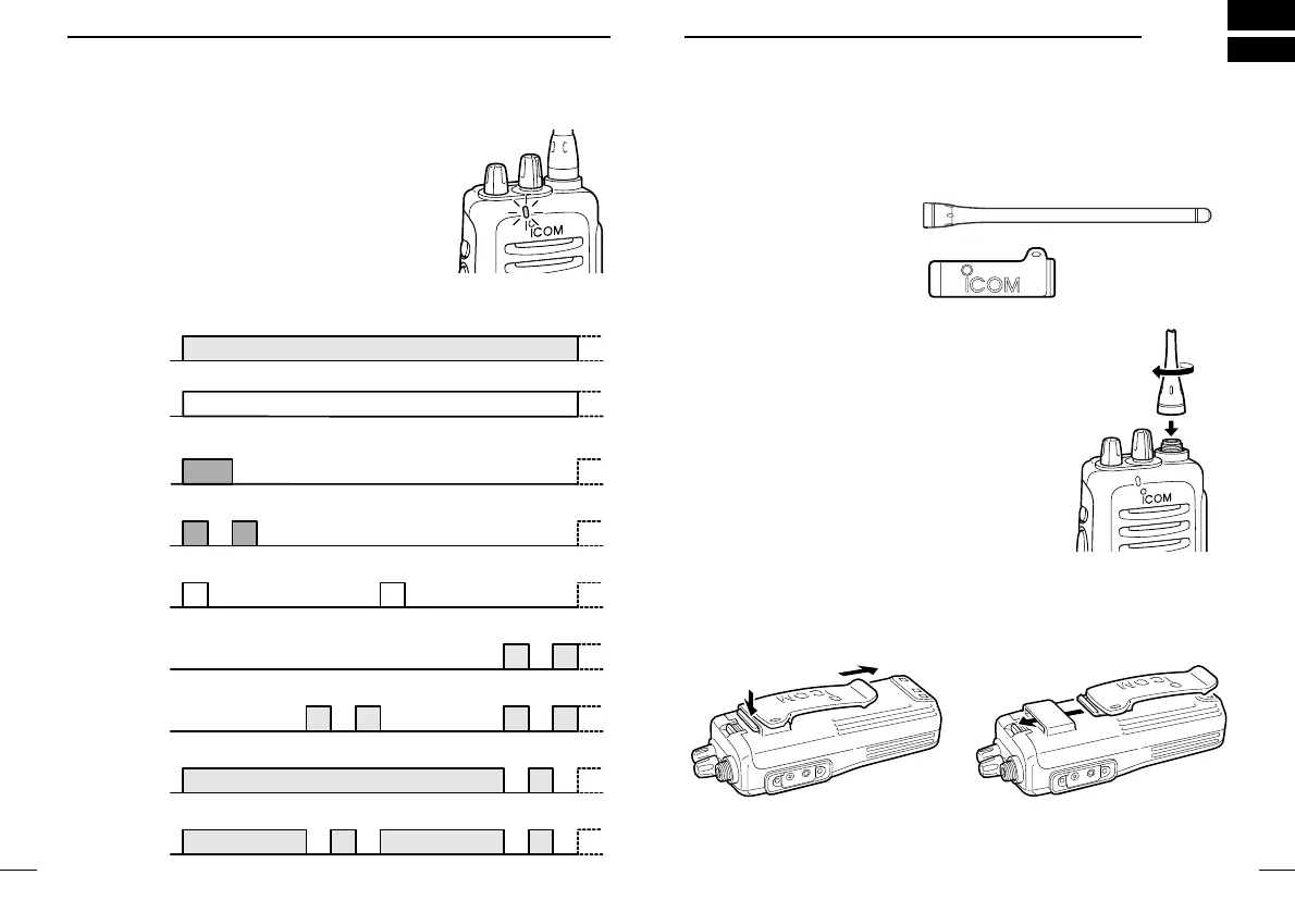
Accessory attachment
D Supplied accessories
The transceiver comes supplied with the following accessories.
q Flexible antenna
w Belt clip
D Antenna
The antenna screws onto the transceiver as
illustrated right.
D Belt clip
Attach the belt clip to the transceiver as illustrated below.
• TX: Turns Red while transmitting a signal.
• RX: Turns Green while receiving a signal.
• Call LED (ON): When receiving a matched 2/5TONE.
• Call LED (Blink): When receiving a matched 2/5TONE.
• Fast/Slow scan: Blinks while Fast/Slow scan is activated.
•Low BATT1: You should charge the battery. (blinks slowly)
•Low BATT2: You must charge the battery. (blinks fast)
•TX low BATT1: Low BATT1 was detected during TX mode.
•TX low BATT2: Low BATT2 was detected during TX mode.

 Loading...