•
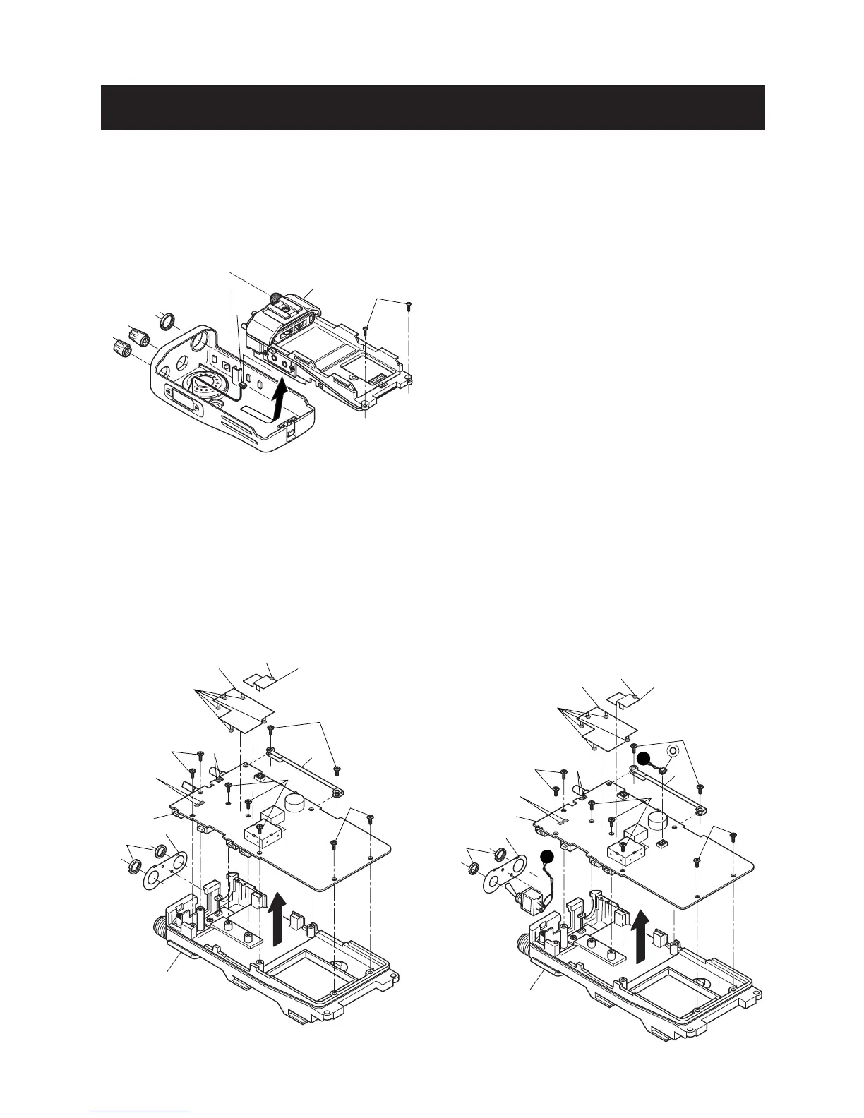
REMOVING THE CHASSIS UNIT
1 Unscrew 1 nut A, and remove 2 knobs *B, C.
2 Unscrew 2 screws D.
3 Take off the chassis unit in the direction of the arrow.
4 Unplug the connector E from the chassis unit.
•
REMOVING THE MAIN UNIT (IC-F24/F25)
1 Unscrew 2 nuts F, and remove the top plate G.
2 Unsolder 1 point H, and remove the earth plate.
3 Unsolder 5 points I, and remove the shield cover.
4 Unscrew 2 screws K, and remove the side plate L.
5 Unscrew 7 screws M.
6 Unsolder 4 points N, and take off the main unit in the
direction of the arrow.
•
REMOVING THE MAIN UNIT (IC-F24S/F25S)
1 Remove the switch connector O.
2 Unsolder 2 nuts F, and remove the top plate G.
3 Unsolder 1 point H, and remove the earth plate.
4 Unsolder 5 points J, and remove the shield cover.
5 Unscrew 2 screws K, and remove the side plate L.
6 Unscrew 7 screws M.
7 Unsolder 4 points N, and take off the main unit in the
direction of the arrow.
 Loading...