5 - 6
5-3 TRANSMIT ADJUSTMENTS
1) Select an adjustment item using [
↑
]/[
↓
] on the PC's keyboard.
2) Set or modify the adjustment value as specifi ed using [
←
]/[
→
] on the PC's keyboard, then push [ENTER].
ADJUSTMENT
TRANSCEIVER’S
CONDITION
OPERATION
ADJUSTMENT
ITEM
VALUE
TX OUTPUT
POWER
(Hi power)
1 • CH. : 4
• Transmitting
• Connect an RF power meter to the
antenna connector. [Power (Hi)] 5.0 W
(L2 power) 2
• CH. : 5
• Transmitting
[Power (L2)] 2.0 W
(L1 power) 3
• CH. : 6
• Transmitting
[Power (L1)] 1.0 W
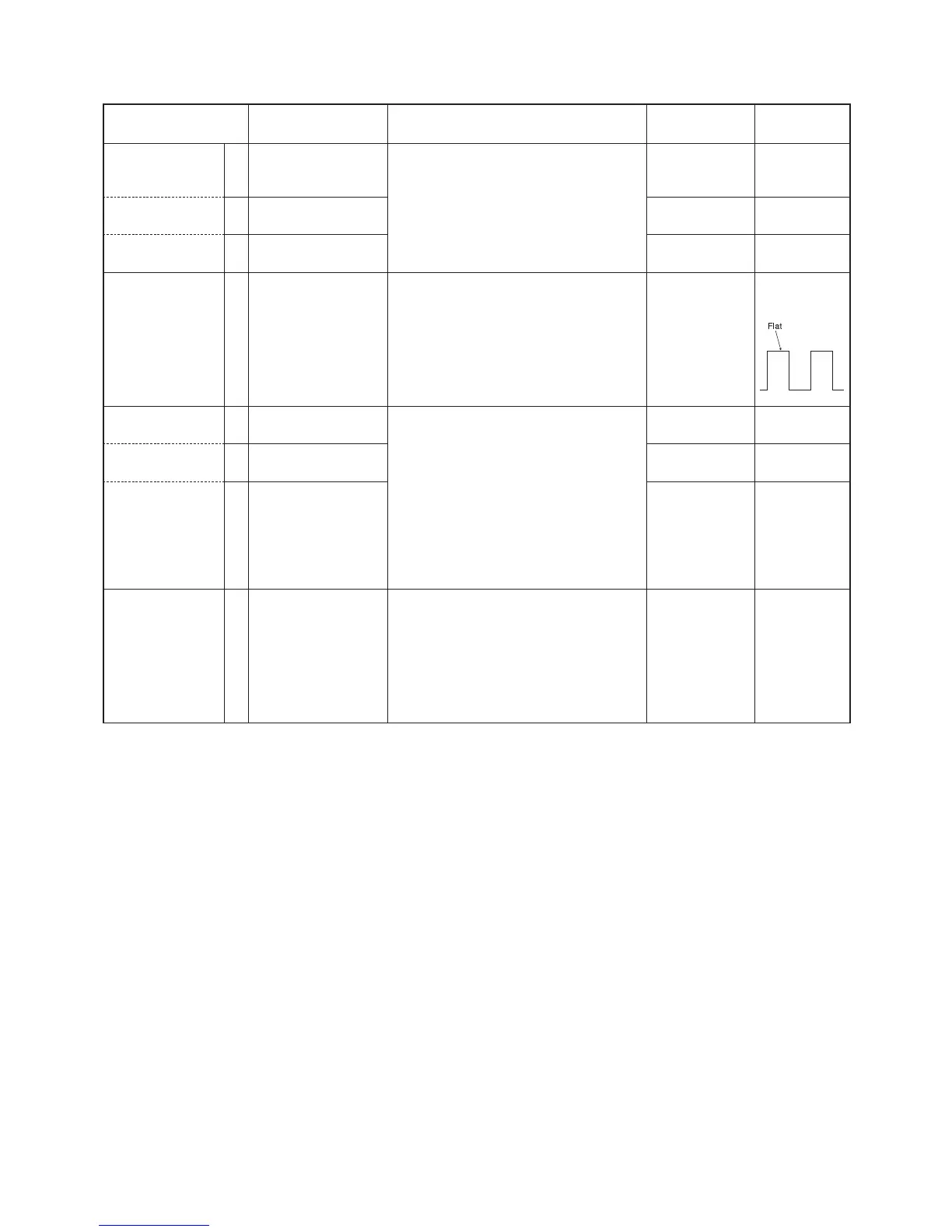
MODULATION
B
ALANCE
1 • CH. : 7
• No audio signals are
applied.
• Transmitting
1) Connect a modulation analyzer with an
oscilloscope to the antenna connector
through an attenuator.
2) Set the modulation analyzer as;
HPF : OFF
LPF : 20 kHz
De-emphasis : OFF
Detector : (P-P)/2
[BAL]
Square
waveform
FM DEVIATION
( Narrow mode)
1 • CH. : 8
• Transmitting
1) Connect a modulation analyzer to
the antenna connector through an
attenuator.
2) Set the modulation analyzer as;
HPF : OFF
LPF : 20 kHz
De-emphasis : OFF
Detector : (P-P)/2
3) Connect an audio generator to the MIC
line through the JIG cable. (See the
page 5-1)
[MOD N]
±2.05 to ±2.15
kHz
( Mid
dle mode)* 2 • CH. : 9
• Transmitting
[MOD Ratio]
±3.25 to ±3.35
kHz
( Wide mode) 3
• CH. : 9
• Transmitting
[MOD Ratio]
±4.05 to ±4.15
kHz
CTCSS/DTCS
DEVIA
TION
1 • CH. : 10
• No audio signals are
applied.
• Transmitting
1) Connect a modulation analyzer to
the antenna connector through an
attenuator.
2) Set the modulation analyzer as;
HPF : OFF
LPF : 20 kHz
De-emphasis : OFF
Detector : (P-P)/2
[CTCSS/DTCS]
±0.65 to ±0.75
kHz
*; [EUR] versions only
 Loading...