M IC-F300/F400/S series
q Turn power OFF, then disconnect the DC power
cable.
w Unscrew the 4 screws, then remove the bottom
cover.
e Cut or desolder the print pattern on the PC board at
the TX mic circuit (A) and RX AF circuit (B).
r Install the unit as shown in the instruction manual.
t Replace the bottom cover and screws, then the DC
power cable.
NOTE:
Modification points are marked A or B on the circuit
board. (see corresponding figures)
A : TX modulation circuit.
B : RX AF circuit.
The scrambler unit may be installed between the mic
amplifier circuit and AF circuit. Cut or desolder the junc-
tion points (or take off jumper chip for IC-F3/F4/S se-
ries).
• Assign the scrambler function to a programmable key
as [SCRM] on [Key & Display Assign] screen, if re-
quired.
• Operation with the [SCRM] key:
− Push and hold to turn the voice scrambler function ON.
− Push to turn the voice scrambler function OFF.
• Program the scrambler function ON/OFF and scram-
bler codes on the [Memory CH] screen, scrambler
type*, group codes*, synchronous capture mode* and
tone start timing* on the [Common] screen with
cloning software when installing this unit. (
*UT-110
only
)
Be sure to resolder above disconnected points, otherwise no TX modulation or AF output is available when you re-
move the scrambler units.
• Some transceiver versions will not be able to
have scrambler units installed because of CPU
revision and other factors. Please confirm that
the transceivers’ serial number is over 50000.
• UT-109 and UT-110 scrambler units require some PC
board modifications. (See below.)
• There are 2 versions (#01: Low AF level type for IC-
F3/F4/S series and #02: High AF level type for the
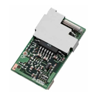
INSTALLATION INSTRUCTIONS
SCRAMBLER UNIT
UT-109/UT-110
Thank you for purchasing the UT-109/UT-110
SCRAMBLER UNIT. The UT-109 and UT-110 are de-
signed for Icom F series VHF/UHF FM transceivers.
Please read these instructions thoroughly before in-
stalling and operating the UT-109/UT-110.
others) for each scrambler unit. Do not install the
wrong version, as they are not compatible.
• IC-F300/F400/S series require the #02 type scram-
bler unit.
• The UT-110 may function as the UT-109 through
cloning software.
• Compatible cloning software: CS-F300S, CS-F300.
IC-F300/F400/S SERIES PRECAUTIONS
PC BOARD MODIFICATION
NOTE FOR REMOVAL