− Push and hold to turn the voice scrambler function ON.
− Push to turn the voice scrambler function OFF.
• Some transceiver versions will not be able to
have scrambler units installed because of CPU
revision and other factors. Please confirm that
the transceivers’ serial number is over 50000.
• UT-109 and UT-110 scrambler units require some PC
board modifications. (See below.)
• IC-F3/F4/S series require a #01: Low level type
scrambler unit. Do not install the wrong version, as
they are not compatible.
• The UT-110 may function as the UT-109 through
cloning software.
• Compatible cloning software: CS-F3.
APPENDIX -1; IC-F3/F4/S SERIES PRECAUTIONS
Be sure to resolder above disconnected points, otherwise no TX modulation or AF output is available when you re-
move the scrambler units.
NOTE FOR REMOVAL
• Program the scrambler function ON/OFF and scram-
bler codes on the [Memory CH] screen, scrambler
type*, group codes*, synchronous capture mode* and
tone start timing* on the [Common] screen with
cloning software when installing this unit. (
*UT-110
only
)
• Assign the scrambler function to a programmable key
as [SCRM] on [Key & Display Assign] screen, if re-
quired.
• Operation with the [SCRM] key:
CLONING
PC BOARD MODIFICATION
M IC-F3/F4/S series
There are 2 types of PC boards are exist. Be sure to
confirm the board number in advance.
• IC-F3/IC-F3S
➥ B4929E requires LCD side and CPU side modifica-
tions.
➥ B4929F*
1
requires CPU side only.
• IC-F4/IC-F4S
➥ B4923G LCD side and CPU side modifications.
➥ B4923H*
1
requires CPU side only.
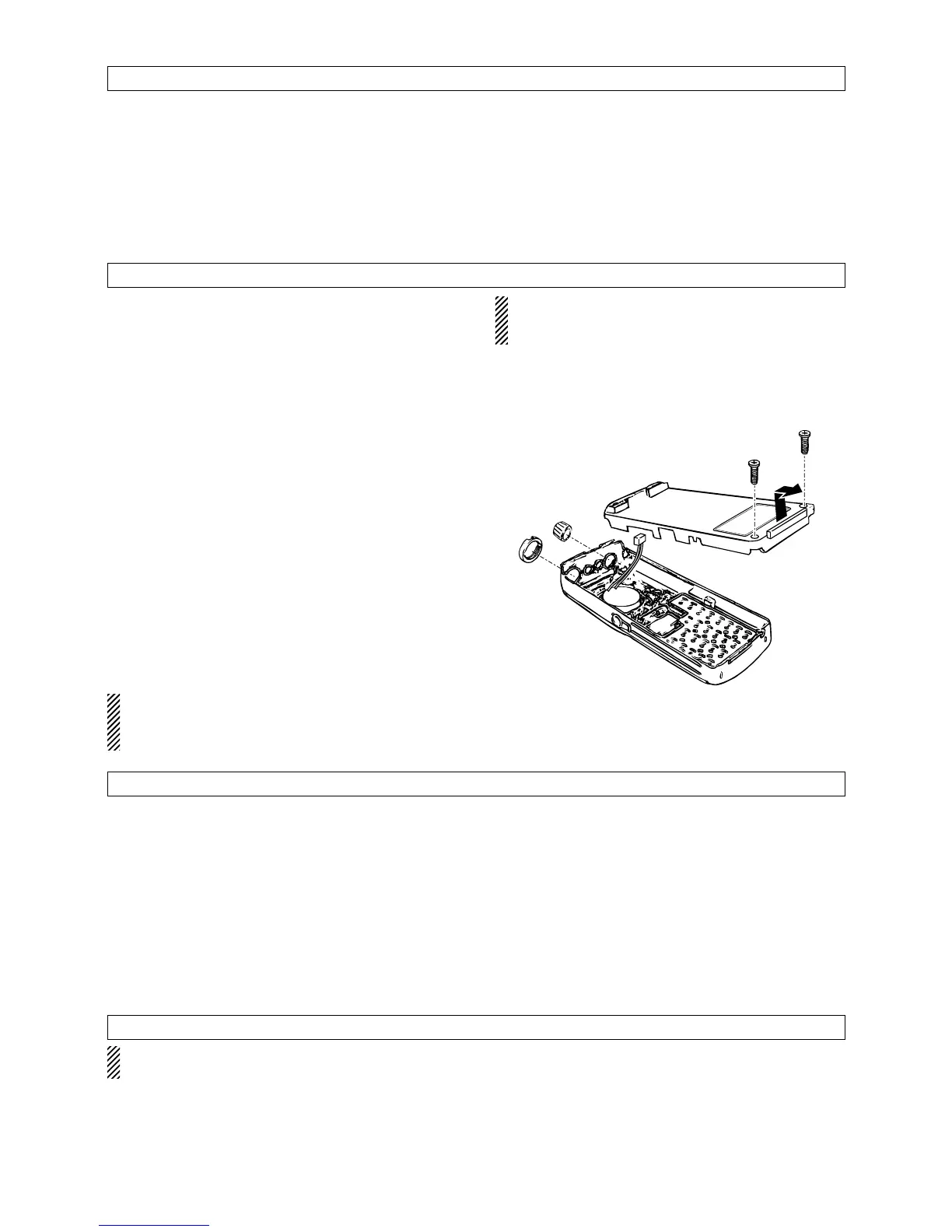
q Take out the knob and unscrew the antenna con-
nector screw.
w Unscrew the 2 screws, then remove the front panel.
e Remove the shield cover if necessary.
r Remove the jumper chip (DET)*
2
or (AF)*
2
on the
LCD side of the PC board.
t Replace the shield cover to the original position.
y Remove the jumper chip resistor(s) on the CPU side
of the PC board. (see right figures)
u Install the unit as shown in the instruction manual.
i Replace the front panel and screws.
NOTE:
*1 B4929F and B4923H's modification points may
access through the service window without take
apart.
*2 Modification points are marked DET or AF on the
main board. (see below figures)
- 3 -
 Loading...