3-1-1
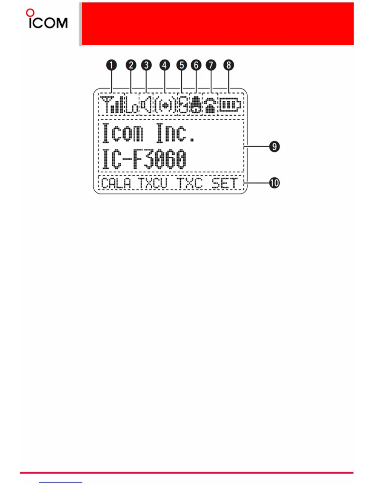
Function Display
21
X SIGNAL STRENGTH INDICATOR
X Indicates relative signal strength level.
Y LOW POWER INDICATOR
Appears when low output power is selected.
Z AUDIBLE INDICATOR
➥ Appears when the channel is in the ‘audible’
(unmute) condition.
➥ Appears when the specified 2/5-tone/BIIS*
code is received.
[ COMPANDER INDICATOR
Appears when the compander function is
activated.
\ SCRAMBLER INDICATOR
Appears when the voice scrambler function is
activated.
] BELL INDICATOR
Appears/blinks when the specific 2/5-
tone/BIIS* code is received, according to
the pre-programming.
^ CALL CODE MEMORY INDICATOR
Appears when the call code memory is selected.
_ BATTERY INDICATOR
Appears or blinks when the battery power
decreases to a specified level.
* BIIS is AVAILABLE for IC-F3061T/S and IC-F4061T/S depending on programming.
Note: Appearance of icons on the LCD display depends on the function used and radio programming.
` ALPHANUMERIC DISPLAY
➥ Displays an operating channel number,
channel name, Set mode contents, DTMF
code, etc.
➥ The indication mode can be selected from 1
line or 2 lines. Ask your dealer for details.
•
In this instruction manual, the LCD illustration is
described using the 2 lines indication mode.
a KEY INDICATOR
Indicate the programmed function of the front
panel keys ([P0], [P1], [P2] and [P3]).
 Loading...